
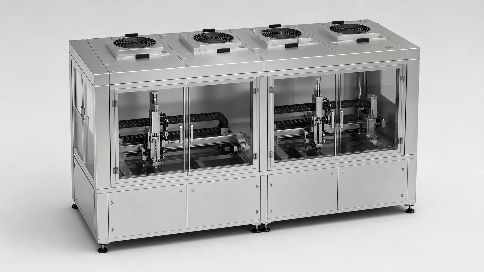
Motionwell Automation designs and builds cleanroom automation equipment in Singapore, which in practice means one of two machines: one that runs inside a classified room without spoiling it, or one that carries its own classified zone and stands anywhere. What the classification itself means, and why it describes the room, is in our guide to ISO 14644 cleanroom classes. The delivered reference for the second is a series of five automated test equipment variants for electronics manufacturers, each with 4 to 6 fan filter units sealed into the enclosure ceiling holding ISO Class 7/8 over the test fixtures while the machine sits in an ordinary factory bay. The first route covers our tray-fed filling and sealing machine, built on a stainless steel frame with a specified product-contact alloy and surface finish for ISO Class 7/8 rooms, and it is the route a multi-station rotary assembly machine takes when it is designed for a Class 7 or Class 8 room, with the dial, the feeders and the press stations all inside the room’s air and built to shed nothing into it. How we design multi-station rotary assembly machines is set out on its own page. Machines are designed, assembled and tested at our Woodlands Link facility, and the company has delivered more than 150 special purpose machines since 2014 under ISO 9001:2015 and bizSAFE Level 3.
The class ratings themselves, and the fuller treatment of coatings, cable jackets and lubricants, are in our cleanroom machine design guide.
Should the Classified Environment Be the Room or the Machine?
This is the decision, and it is made on how much of the product’s route genuinely needs classified air. Three arrangements are available.
The machine lives inside a classified room. The facility holds the class, and the machine’s job is to not spoil it. This is what our tray-fed filling and sealing machine is built for.
The machine carries its own classified zone. Fan filter units in the machine’s own ceiling push filtered air down over the process, the enclosure is held positive against the factory, and the classified volume exists only where the product is. This is the delivered test equipment series.
Both, split by class. The room holds a lower class over the whole area and the machine holds a tighter one over the product. That suits a process needing controlled space for people and material flow, with one step needing more than the room economically provides.
| Machine inside a classified room | Machine carrying its own zone | |
|---|---|---|
| What holds the class | Facility air handling, sized for the whole space | Fan filter units on one enclosure |
| What the machine must be | A non-contaminating object inside someone else’s budget | A non-contaminating object, and the air handling as well |
| Where the money goes | Building work, air handling capacity, gowning and airlocks, and the recurring cost of keeping the room qualified | Filters, a gasketed ceiling, pressure monitoring, and a more expensive enclosure |
| Cost of the second machine | Lower, because the room is already paid for | The same again, because each machine buys its own envelope |
| Who owns the particle number | The facility, with your machine inside the total | Us, inside our enclosure, against the factory outside it |
| Operator access | Gowned entry, an airlock, a materials route | An enclosure door and a loading opening |
| Fails when | The room passes at rest and fails while the machine runs | The product has to leave the enclosure between steps |
Two asymmetries decide more of this than the capital comparison does.
The first is what happens to the second machine. A room is a fixed cost paid once, so the marginal cost of putting another machine into it is low, and a plant already running classified space is usually better off using it. An in-machine envelope does not amortise: each machine buys its own filters, gasketed ceiling and pressure monitoring, so the arithmetic favouring the enclosure on machine one is weaker on machine three.
The second is the product’s route. An in-machine zone protects the product where the machine holds it and nowhere else. If the part is exposed between stations, moves to a second machine, waits in a rack or gets inspected off-line, every one of those handovers sits outside the envelope you paid for. Trace the whole path with a pen before choosing, and count the exposures.
This is a concept-stage decision, because it changes the machine itself. The in-machine envelope changes the enclosure design, the path the air takes through it, where the cables run and how maintenance access is arranged. Those four are the frame. By the time the frame is welded the envelope is decided, and revisiting it means a new frame, new cable routing and new actuators, which is most of a new machine.
What Changes When the Fan Filter Units Go Into the Machine Itself?
The guarding also becomes a controlled positive-pressure enclosure. Filtered airflow, leakage paths and access openings must work together to maintain the required environment over the product. Verify airflow and differential pressure with the machine in its operating configuration.
On the delivered test equipment, 4 to 6 fan filter units are sealed into the enclosure ceiling with continuous gaskets, air leaves through filtered return at the base, and the enclosure is held positive against the factory bay so that leakage runs outward. That last property is what makes the arrangement work, and what makes every opening expensive.
Here is the trade: every service panel is a leak path, and every sealed panel is a maintenance problem. You cannot have neither, so the design question is which openings you keep and where they go.
| Boundary choice | What it buys | What it costs |
|---|---|---|
| Welded or permanently sealed panel | The tightest boundary, no gasket to age, nothing an operator can leave open | Whatever is behind it can only be reached by dismantling, so nothing that wears may live there |
| Gasketed, bolted access panel | Service access with a boundary that is reliable while the bolts are in | A gasket with a life, and a panel someone can refit badly at two in the morning |
| Hinged interlocked door | Fast access for clearing faults, and the guarding function at the same time | The most-used opening on the machine, so it is the seal that ages fastest and the one to specify hardest |
| Loading or transfer opening | Product gets in and out without opening the machine | A permanent hole in the boundary, to be positioned and sized against the airflow |
| Service point outside the boundary | Maintenance without breaking the envelope at all | Longer cables and tubing, a bigger footprint, and a machine split across a wall |
Where an axis must cross that boundary, it crosses through a sealed bellows or a glanded penetration.
Reducing the number of openings is a layout decision, and the delivered machine shows what that looks like. The test equipment uses a circular pallet transfer that returns every specimen to a single load and unload station, so one collaborative robot serves the whole machine and only one opening has to be made in the enclosure. The station count is then fixed by the loop geometry, which is what that choice cost. The rest of that architecture is on our automated test equipment page.
Two consequences follow the units into the specification and are easy to leave out of it. Overall height grows, because they sit above the working level and the room has to clear the machine plus its ceiling. And they draw power and make noise continuously, in a space where both are budgeted.
Because the same panels are safety guards and contamination boundaries at once, the guarding layout and the airflow layout have to be resolved together, alongside the risk assessment described on our machine safety and compliance page.
Which Way Does the Air Move, and What Does That Do to the Station Order?
The air moves down over the product, then out at the base. The rule that follows reshapes layouts: the product path has to be upstream of anything that sheds, and upstream in a downflow machine means higher, and earlier in the flow.
That single rule sorts the machine vertically. The open product, the nest and the tooling that touches it sit in clean air at the top of the flow. Guides, screws, belts, gearboxes, cable carriers and pneumatic exhaust sit below the product plane or behind the boundary, so what they shed is carried away from the part. A mechanism that must work above the product is the expensive case, and it gets a sealed housing with local extraction.
| Where it sits in the flow | Typical occupant | Consequence | What to do instead |
|---|---|---|---|
| Above the product | Overhead tooling, a Z-axis screw, a cable carrier crossing the ceiling | Whatever the mechanism sheds lands on the open part, every cycle | Seal and extract locally, or move the axis to the side and reach in horizontally |
| Beside the product, in the flow | Tall fixtures, guards, a badly placed cable tray | Creates a shadow the downflow does not reach, which shows up under motion | Keep the volume over the fixtures clear, and check tall items against the flow path on the layout |
| Below the product plane | Drives, belts, transfer mechanism, exhaust manifold | Correct, because the flow is already carrying particles that way | Nothing, this is where the mechanism belongs |
| At the boundary | Loading opening, reject chute, operator door | Room air enters here whenever the pressure differential is smallest | Put openings downstream of the process |
One ordering rule comes out of the same physics and is worth applying to the station sequence: put the step that exposes the product as early in the air path as the process allows, so it is not working in air that has already passed over four other stations.
Where the process forces the wrong order, the answer is a barrier and local extraction. Adding fan filter units to overwhelm a source you could have moved is a running cost paid forever to dodge a layout decision that was free at concept.
Where Do the Particles Come From, and What Do You Substitute?
Anything that slides, rolls, meshes, flexes or exhausts is a source. The substitutions matter more than the list, so here they are with their costs.
| Source | Substitution | What the substitution costs |
|---|---|---|
| Recirculating guides and ball screws | Bellows or covers over the mechanism, sealed low-particle variants with wipers, cleanroom grease | Harder visual inspection, added moving mass, longer procurement on the sealed variants |
| Timing belts and gear trains | Enclose the drive train, or move it below the product plane | Longer transmission paths, and more structure to hold stiffness |
| Cable carriers | Continuous-flex cable rated for the travel inside a cable chain, jackets chosen for low shedding, stainless ties | Cable cost, bend-radius discipline, and a route that has to be drawn |
| Pneumatic cylinders exhausting to atmosphere | Cleanroom-rated cylinders with the exhaust piped back to a manifold outside the clean zone | Return tubing on every cylinder, a fuller cable carrier, and a changed pneumatic schematic |
| Motor and drive cooling fans | Drives outside the enclosure, sealed motors inside | Longer shielded motor cables and a separate control cabinet, which changes the footprint |
The reasoning reaches into parts nobody thinks of as particle sources. On the test equipment the specimen nests are machined from PA66 nylon and POM, partly because surface resistivity above 10^12 ohm keeps the fixture from loading the device under test, and partly because a non-metallic nest does not shed conductive particles into a Class 7/8 envelope. The cost comes in the same breath: engineering plastics creep under sustained clamping load, so those nests are consumables with a defined replacement interval. The tooling side of that argument is on our end of arm tooling page.
What Does Your Cleaning Regime Decide About Materials and Finish?
It decides more than the class number does. A surface specification answers two questions: how is this surface cleaned, and how much residue may survive that cleaning. The ISO class tells you neither.
| Cleaning regime | Contact and external surfaces | Seals and elastomers | What breaks first |
|---|---|---|---|
| Manual wipe with isopropanol or a quaternary disinfectant | Smooth, wipeable, crevices designed out, reachable in one pass | Chosen against the disinfectant, because the disinfectant is what attacks them daily | Labels, gaskets, and any surface a wiper cannot reach in one pass |
| Hose-down washdown | SUS304 or 316, with the surface finish set against the residue limit, and an enclosure rating chosen for the hose | Sized against water ingress as much as against chemistry | Enclosure penetrations and cable glands |
Two consequences are worth acting on. Product-contact parts that come off without tools get cleaned properly, because cleaning stops queuing behind a technician looking for a spanner. And the chemistry belongs in the user requirement specification as a named compound, one of the lines discussed on our writing an automation URS page. The delivered machine is on the filling machines page and in the filling and sealing machine case study.
None of it works without the geometry behind it, drawn in: no blind holes, no lap joints, no exposed bolt heads.
How Does the Machine Get Into the Room?
This is the constraint discovered late, and it is a design input. The machine has to arrive through the doors and around the corners that exist, in the sections it ships in, and those sections are decided in the same weeks as everything else here.
Scale is why it bites. Our tray-fed filling and sealing machine occupies roughly 3 m by 1 m by 2 m, with the feed tray at one end and the discharge tray at the other. A machine of that size is still a two-metre object crossing a classified boundary, and fan filter units on the roof make it taller.
| Constraint | Where it is measured | What it decides |
|---|---|---|
| Narrowest doorway or equipment airlock on the route | The route, including door furniture and frames | How many sections the frame is split into |
| Lift car dimensions and rated load | The lift the machine will actually use, on the day it will use it | Whether an upper floor is reachable at all, and in what pieces |
| Corridor corners and turning geometry | A plan view with the longest section drawn on it | Section length, which is often set by a corner |
| Floor loading | Distributed load, and the point loads under the feet | Whether the slab takes it, particularly above ground level |
| Clear height under building services | Under the lowest duct, sprinkler and cable tray on the route | Machine height including the fan filter units on top |
| Access hours | The plant’s shutdown and weekend windows | The installation programme, since rigging, power and safeguarding do not happen mid-shift |
Every split line has a price on both sides of the wall. A joint in the frame is re-aligned, re-levelled and re-commissioned on site, and on a machine carrying its own envelope it is also a gasketed joint to be re-made and proved inside the room. Assembling in a classified space brings people, tools and packaging with it, so the crating stops at the boundary and the machine is cleaned before it crosses. That belongs in the programme, and never in the goodwill of the installation week.
None of this is unique to a locally built machine. Rigging equipment into a unit with a tight door and a lift with a weight limit costs what it costs wherever the machine came from, one of the rows in the comparison on our local versus overseas machine builder page. What is avoidable is learning the door dimension at the end of the build, and a photograph of the route at enquiry stage is usually enough to catch it.
Who Has to Gown to Touch the Machine?
Whoever the room’s protocol names, and that answer carries a cost per event that lands in maintenance.
The arithmetic is simple, and it belongs in the comparison. Every intervention inside a classified space carries the gowning routine before it and the re-clean after it, and so do the tools and the spare part, which come in through a pass-through or an airlock. A five-minute fault does not cost five minutes. It costs five minutes plus the boundary, twice.
Three design consequences follow, and all of them are cheap at concept.
Split the machine at the boundary. Everything touched often belongs outside it: the drives, the air preparation, the pneumatic manifold where the schematic allows. On the test machines we have delivered, the valve banks sit centrally inside the enclosure with regulated air preparation at each bank, so on a new build the question worth asking early is which of those banks could sit on the non-clean side instead. A manifold inside the clean zone is a heat source, a particle source and a gowned entry every time a solenoid or a filter bowl needs attention. Moving it out costs tube length, and longer tubes cost response time on every short stroke, which is a trade worth making on a concept drawing and expensive to make once the schematic is built.
Make the consumables the shortest visits. Filters, nests, seals and grease points are the recurring reasons anyone enters. Ask for the consumable list, the interval and the access route together, because an interval that reads reasonably on paper reads differently once each occurrence is a gowned entry.
Write the recovery step before it is needed. Any panel opening into the clean zone gets a documented re-clean, and on a qualified machine a documented return to service. Without that procedure the machine can leave its qualified state the first time it is serviced, and the gap may not surface until an audit.
How Is the Machine’s Own Environment Proved, and Who Owns the Number?
It is proved by measuring it while the machine works, and by agreeing who owns the number before anyone measures.
At rest, almost any machine passes. The meaningful measurement is taken with the axes moving at production speed and the cylinders firing, which matters most where the product is a bare wafer, as on our wafer handling automation page, and is why particle verification belongs in performance qualification. A machine at rest, one running empty and one running product with people present are three different results, and the specification has to say which the acceptance criterion refers to.
Ownership splits cleanly if it is written down. The room’s classification belongs to whoever built and maintains the room. The environment inside our enclosure is ours, measured against the factory air outside it. The interface is the pressure differential and the openings, and the interface is what gets argued about when a number disappoints, so name it in the contract.
One useful consequence follows for a machine carrying its own zone: the envelope can be proved at factory acceptance testing at Woodlands Link, because the enclosure brings its own air with it. A machine destined for a room cannot be fully proved before it is in the room, so its acceptance splits across factory and site testing, and the sampling points and criteria have to be agreed early enough to decide where the sampling ports and access panels go.
What the evidence pack contains depends on the regime the machine is bought under. For a machine bought under a GMP regime, the pack we prepare is an IQ/OQ/PQ package structured under GAMP 5, with executed test records, a validation summary report, and material certificates and surface finish records for product-contact parts. The mechanics of that pack are on our computer system validation page. Where the resulting records are retained as GMP electronic records, 21 CFR Part 11 governs how they are stored, who may alter them and what audit trail follows, which is a documentation project running alongside the build.
When Is a Machine-Carried Clean Zone the Wrong Answer?
The process is bigger than an enclosure can sensibly be. An enclosure a person has to walk into is a small room with worse airflow and no gowning discipline. At that size, build the room.
The product has to be reached constantly. Every opening cycle breaks the boundary, and a machine whose door is open half the shift is not holding anything.
The class is being specified upward for comfort. If the product needs Class 8, buying Class 5 sealing produces a machine that is harder to maintain and no better yielding. Specify against the product’s requirement and the cleaning regime in the room.
The machine already exists. Making a built machine cleanroom-compatible rarely works, because the frame material and finish, the fastener style, the cable routing and the actuator choice are frame-level decisions. Where a retrofit is genuinely the right route, what that scope actually contains is on our retrofit versus replace page.
A standard machine with a cleanroom option already covers the process. Where one does it at a lower price than anything we would build, that is the comparison to run first, and it is on our custom machine versus standard equipment page.
What Has to Be Settled Before the Frame Is Welded?
Run these in order. The first hard answer usually settles the route.
- Where on the product’s path is it actually exposed? Mark the exposure points on a route drawing. One points at an enclosure. Five across three machines points at a room.
- What class does the product require, and on what evidence? A requirement from a customer specification, a regulator or a yield study is a number. A preference is not.
- What is the cleaning regime, named as a chemistry and a frequency? This sets the surfaces, the seals and the labels more directly than the class does.
- What has to happen above the product? Overhead tooling and overhead axes are the expensive case, and knowing early is what keeps them affordable.
- Which interventions recur, and can they happen outside the boundary? Every one moved outside is a gowned entry you never pay for.
- What is the route in, in millimetres? The narrowest door, the lift, the corner, the slab, and the height under the services.
- Who owns which particle number, and when is each one measured? Room, enclosure, factory acceptance, site acceptance, performance qualification.
| Your situation | Start from | Why |
|---|---|---|
| One process step needs the class, the rest of the plant does not | Machine-carried zone with fan filter units | The classified volume ends up where the product is, and nowhere else |
| Product moves between machines and people while exposed | A classified room, with non-contaminating machines inside it | An envelope over one station protects the wrong interval |
| A qualified room already exists and has capacity | A machine built to live in it | The expensive part is already built and paid for |
| Operators need a controlled space, one step needs more | Room at the lower class, enclosure at the tighter one over the product | Buy the tighter class only over the volume that needs it |
| An existing machine that has to move into classified space | A survey of the frame, the finish, the cabling and the actuators before a quotation | Cleanroom compatibility lives in the frame, so the survey decides whether a retrofit exists at all |
Lead time runs 16 to 24 weeks from concept approval to factory acceptance testing on a standard build, and 24 to 32 weeks where cleanroom compatibility or full validation documentation applies. Design, fabrication, assembly and testing happen at Woodlands Link with an in-house design team of eight, which is why a Singapore buyer attends the factory acceptance test without flying to it. That matters here because the acceptance test is where a particle count under motion either holds or names the axis that does not. The delivered work sits in context on our electronics and semiconductor automation page, our medical device automation page and our pharmaceutical packaging page, and the enclosure is documented in the cleanroom ATE case study.
Frequently Asked Questions
Does automating a cleanroom process reduce the number of people who have to gown up?
Usually per shift, and never to zero. Automated handling removes the operators who were moving product between steps, which is one of the reasons this equipment gets bought. What it does not remove is entry: somebody still loads consumables, clears faults, changes filters and replaces wear parts, and those entries are less predictable than a production shift. What you are trading is a known number of gowned production hours for a smaller and less predictable number of gowned maintenance hours, which is why the intervention list belongs in the specification.
Who maintains the fan filter units, and how often?
Your maintenance team, on an interval driven by loading. A filter loads as it works, the pressure drop across it rises, and the fan compensates until it cannot. That is why differential pressure monitoring belongs on the enclosure as an instrument somebody reads: it is the signal that a filter change is due before the class drifts. Ask any supplier for the filter part number, the differential pressure that triggers a change, whether the filters come out from above the ceiling panel or from inside the enclosure, and what the re-clean step is afterwards.
Should the control cabinet sit inside the cleanroom or outside it?
Outside, wherever the cable lengths allow, because the cabinet is where the frequent interventions happen. Drive faults, resets, parameter changes and program work are the interventions that recur, and every one of them costs a gowning cycle if the cabinet is inside. What moving it out costs is real and should be priced: longer shielded motor cables, a wall penetration that has to be sealed and stay sealed, and a machine split across a boundary at installation. Settle it while the layout is being drawn, because it decides where the cable route runs.