
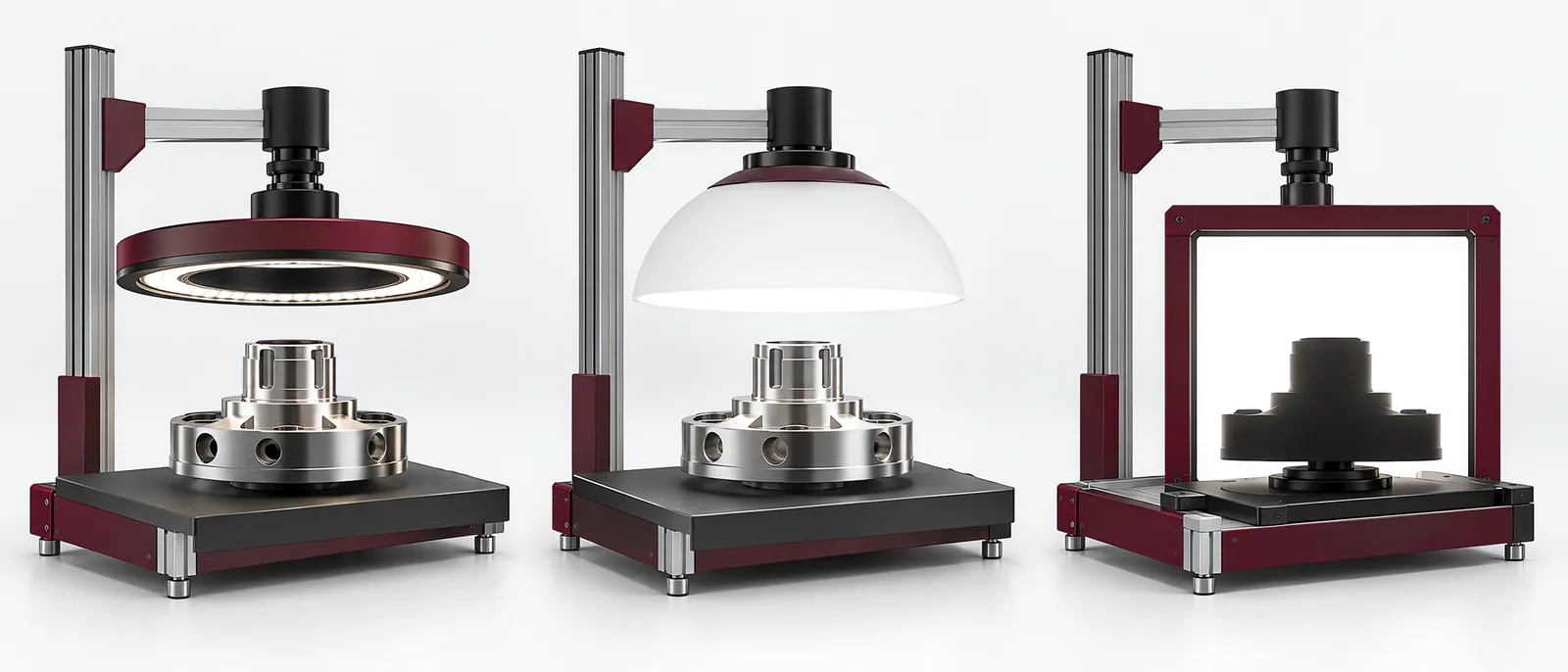
Conceptual equipment illustration.
LED lighting for machine vision should make the required feature distinguishable across the production samples. More brightness will not fix a geometry that sends glare into the lens or hides a shallow scratch. Compare lighting arrangements with the same camera and parts before selecting the light unit.
For a machine vision inspection system, the purchase decision is about the image created by the light, lens and part together.
Choose the Contrast You Need
A low-angle light can make surface marks scatter light towards the camera while a smooth surrounding area stays dark. CCS’s low-angle strobe application brochure shows this approach for scratch inspection. That example supports a trial geometry; it does not establish that every scratch on every surface will be visible.
Use these arrangements as test candidates:
| Feature | Candidate arrangement | Question for the sample trial |
|---|---|---|
| Outer profile | Backlight behind the part | Is the edge stable across height and orientation? |
| Scratches on a reflective face | Low-angle or dark-field illumination | Do real defects remain distinct from machining texture? |
| Printing on a curved shiny part | Diffuse illumination | Can glare be reduced without losing character contrast? |
| Flat reflective markings | Coaxial illumination | Does the feature still contrast when the surface tilts? |
A translucent part or textured coating may reverse the expected result; retain only the arrangements that separate the real sample set.
Keep the Trial Comparable
Prepare acceptable samples as well as defective ones. Include the finish, colour and geometry variations that the line will encounter. Compare illumination angle and distance while recording exposure, lens aperture and camera gain.
Do not select a light from one unusually clear image. Look for separation between the least visible defect and the most difficult acceptable surface. The surface-defect inspection scope explains why the defect boundary needs to be agreed before threshold selection.
For dimensional work, compare measured edges across repeated positioning. The inline dimensional measurement guide addresses the measurement chain beyond a visually sharp image.
Add Motion and Thermal Conditions
Strobe timing must overlap the camera’s exposure. Test trigger delay and pulse width with the intended shutter mode, not only a continuously illuminated stationary part.
Use the light manufacturer’s permitted duty cycle and controller combination. Higher pulse output is not a universal continuous operating rating. Run the equipment until its operating conditions stabilize, then repeat the image comparison. Record mounting position so that maintenance can restore the tested geometry.
The complete vision-inspection guide connects this trial to acceptance and rejection. Contact Motionwell to discuss the feature or surface that is difficult to image.