
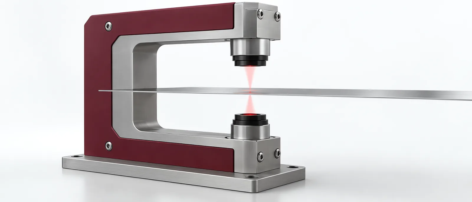
Conceptual equipment illustration.
A thickness measurement system must identify the separation of two material surfaces. A displacement sensor looking at one surface usually reports its position relative to the sensor; it cannot separate thickness change from part movement unless a valid reference or suitable material-specific method supplies the missing information.
This distinction matters when integrating measurement into a machine vision and inspection system. The inline dimensional measurement scope covers datum selection and handling for other dimensions.
Write Down the Measurement Geometry
For an opposed-sensor arrangement, thickness can be calculated from the calibrated gap between the sensors minus the two measured surface distances. Micro-Epsilon’s thicknessSENSOR manual describes that two-sided optical arrangement for non-transparent strips and plates.
An illustrative calculation is:
Thickness = 100.00 mm reference gap − 48.80 mm upper distance − 48.20 mm lower distance = 3.00 mm.
This is a geometry example, not a claimed measurement uncertainty. The reference frame, sensor calibration, alignment and surface response still affect the result.
Both sensors need to observe corresponding locations at corresponding times. A tilted or moving sheet can defeat a calculation assembled from mismatched readings. Check usable measuring ranges throughout the allowed part movement.
Do Not Make Two Sensors a Universal Rule
A contacting gauge can establish two surfaces mechanically. Some optical methods can resolve multiple interfaces in suitable transparent materials from one side. Other arrangements use a known substrate or support as the reference. Select the method from material properties and access; do not apply the opposed-laser example to every film, coating or laminate.
If a support roll is the reference, include its runout and any gap between the material and roll in the trial. If the frame spans a hot process, compare readings after temperature stabilization.
The 2D versus 3D vision guide helps establish whether the inspection needs an image, height profile or direct thickness channel. A surface profile alone does not necessarily expose the second surface.
Validate with Moving Material
Use reference samples covering the intended thickness range, then repeat readings at several positions and orientations. Compare stationary and moving measurements. Record the speed, sampling interval and filtering; smoothing can hide a narrow local change that matters to the product.
Include unavailable readings in the machine logic. A no-return or out-of-range condition should not be silently replaced with the last acceptable thickness. Tie each result to the correct part or strip position, using the record structure of the automated test equipment.
Contact Motionwell about the measurement, whether the requirement is a discrete component, moving strip or coating on a known substrate.