
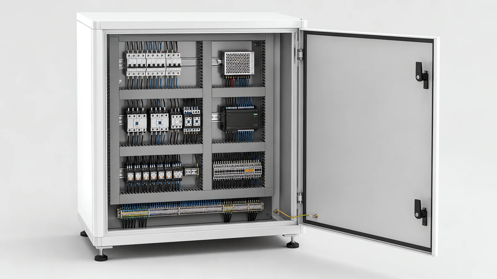
Motionwell Automation designs and builds the control panels for the machines we make in Singapore, and this page is about the cabinet as a deliverable, with the logic that runs inside the controller covered on its own page. Delivered work sets the range. On the tray filling platform the enclosure is sealed, with no fan, because the line gets hosed down daily. On the 5-axis CNC shot peening machine for turbine blade treatment the control cabinet is a free-standing unit carrying the operator terminal on its door, and the dust extraction gear sits in a separate enclosure beside it so that filter work never opens the control cabinet. Panels are built, wired and tested with the machine at our Woodlands Link facility, and the company has delivered more than 150 special purpose machines since 2014 under ISO 9001:2015 and bizSAFE Level 3.
The component list inside a panel we build is normally your plant standard, because the spares and the programming tools have to be the ones your maintenance team already holds. Where accredited LVD and EMC test reports are needed, we arrange them with an external laboratory and fold the reports into the file. Panels are built as part of a machine we are designing or modernising, so the cabinet, the sequence and the safety circuit are drawn together.
Two neighbouring scopes have their own pages. Choosing and programming the controller that holds the machine sequence is on our PLC migration and upgrade page, along with the four strategies for getting off an obsolete one. The risk assessment, the performance level argument and the validation behind the safety circuit are on our machine safety and CE marking page.
Where a machine connects to an existing process plant, agree the control boundary before specifying the panel interfaces. Our DCS versus PLC comparison explains which functions stay with the machine and how it exchanges commands and status with the plant control system.
What Does a Control Panel Have to Do Besides Hold the Components?
Four things, and only the first is obvious. It has to shed the heat its own contents make. It has to keep out whatever the room throws at it. It has to be workable by somebody who did not build it, at three in the morning with a shift waiting. And it has to still be legible in ten years, when the drawings are the only witness left.
Those four pull against each other, which is the design problem. Sealing the box against water makes heat harder to get rid of. Packing it tighter to save floor area makes it harder to work in. Adding a cooling unit adds a component that can fail. None of them is a specification to be maximised, and a panel drawn from a bill of materials alone tends to be wrong in a way nobody notices until the second hot afternoon.
One assumption belongs in the design. Somebody will one day open this panel while it is live. Not because they should, but because a fault that only appears when the machine is running cannot be found with the isolator off, and whoever finds it will be under time pressure. A panel designed as though that never happens is the one that makes it dangerous when it does.
Application details change the cabinet scope. Hipot testing equipment brings high-voltage switching and test-access interfaces; industrial energy monitoring adds a defined metering boundary and sensor configuration. Where the controller platform is still open, compare Siemens and Allen-Bradley systems on a matched I/O, software and maintenance scope.
What Is an Open Industrial Control Panel?
An open panel is the assembly without a box of its own: a back plate carrying the DIN rails, ducting, breakers, contactors, power supply, controller and terminal rails, wired and tested as a unit, then mounted inside something else. Enclosed means the same plate in a rated enclosure. What open removes is the box, and with it the contact and ingress protection the box provided, so those duties pass to whoever supplies the enclosure it goes into.
Why Does Enclosure Size Follow Dissipated Watts, Not Component Count?
Because the enclosure is a heat exchanger before it is a container. A sealed box sheds heat through its surface at a rate set by the area available and the difference between the temperature inside and the air around it, and the limit inside is set by the least tolerant component in there. So the sizing calculation is a balance: add up what everything dissipates, compare it against what the surface can shed at your ambient, and if the two do not meet, the box gets bigger or it gets a cooling method.
Counting components predicts the length of DIN rail and almost nothing else. Two panels with the same device count can differ by an order of magnitude in dissipation, because one holds a row of servo drives and the other holds a row of relays. Drives, power supplies, transformers and anything converting or switching real power are where the watts are, and they are also items often added late in a project, which is how a cabinet that balanced at concept stage stops balancing by the time it is built.
The ambient in that calculation is the one beside the machine. A panel next to an oven, in an unconditioned bay under a metal roof, or pushed against a wall with no clearance behind it, starts from a higher temperature than the datasheet assumed, and the whole margin lives in that difference. The symptom is characteristic: a machine that faults on a hot afternoon and runs cleanly the next morning is a thermal problem, because past its rated temperature a drive derates its current and a controller reports a fault, and never says it is hot.
| Cooling route | What it does | What it costs | Where it fits |
|---|---|---|---|
| Larger enclosure, natural convection | More surface to shed through, with no moving parts and no filter | Floor area and cabinet cost, both usually scarce | Modest dissipation, and any panel where an extra maintenance item is unwelcome |
| Filtered fan and exhaust louvre | Forces room air through the box, which is cheap capacity per watt | The ingress rating drops to whatever the filter and louvre allow, and the filter becomes a scheduled item | Reasonably clean bays where the box is allowed to breathe |
| Air-to-air heat exchanger | Moves heat out without exchanging air, so the inside stays sealed | Less capacity than a fan of similar size, and it can only push the inside towards ambient, never below it | Sealed panels in a room whose ambient sits comfortably below the internal limit |
| Refrigerated enclosure cooling unit | Holds the inside below ambient with the box still sealed | The most capable and the most expensive, and it can fail quietly while the machine keeps running | Sealed panels in hot spaces, and high dissipation that nothing else will carry |
| Move the heat out of the box | Drives, a transformer or a vision PC placed in their own enclosure | A longer, shielded motor cable and a second cabinet, which changes the machine footprint | Classified environments, and panels where a few components dominate the total |
Some of those rows add a maintenance item, and the cooling unit is the worst of them because it can stop working without announcing it, the same warning we give about a vision PC’s enclosure cooler on our smart camera versus PC-based vision page. Choose the route at cabinet layout, because each one changes the footprint or the maintenance schedule.
How Do You Choose an Ingress Rating Without Cooking the Panel?
You take it from the environment the panel will actually stand in, and that survey takes a walk. Is the space hosed down or wiped? Is there conductive dust, abrasive dust or oil mist? Does the roof leak in a heavy afternoon? Is there a cleaning chemistry, and does anybody aim it? Is the bay air conditioned, and does it stay that way at night and at weekends? The answers set the rating; a habit does not.
Then the trade that governs everything else on this page: a sealed cabinet is a thermal problem. Once the box cannot breathe, every watt inside has to leave through the wall or through a unit bolted to it, so sealing and cooling are one decision taken twice. That is why over-specifying costs real money in both directions. A washdown rating on a panel in a dry bay buys a hotter cabinet that is harder to work in, for no protection anybody needed.
| Environment around the cabinet | What has to be kept out | What that does to the cooling decision |
|---|---|---|
| General factory bay | Dust and casual contact with live parts | A filtered fan usually carries it |
| Daily washdown on a hygienic line | Directed water and cleaning chemistry, from angles nobody plans for | Sealed, with the rating taken from the sanitation procedure. The tray filling platform is built for exactly this, so heat leaves through the wall or through a closed unit |
| Cleanroom or classified zone | Particles generated inside the box as much as anything outside it | Sealed, and the heat is taken out of the clean zone |
| Blasting, grinding and machining swarf | Abrasive and sometimes conductive dust, plus coolant mist | Sealed, and sited away from the discharge. On the shot peening machine the control cabinet stands as its own unit with extraction in a separate enclosure |
| Unconditioned or outdoor space | Water and dust, plus a daily temperature swing that brings condensation with it | Sealed, then heated: an anti-condensation heater with a hygrostat, and cable entry from below |
The last row is the one that surprises people, because the instinct when water appears inside a sealed panel is to seal it harder. Water that condensed inside the box did not come through the wall; it came out of the air already in there when the panel cooled overnight, and it collects on the coldest metal available. Heat fixes that and more silicone does not. The sealing and material discipline for classified builds, a different problem aimed at a different risk, is in our cleanroom automation guide.
Why Does Layout Decide Noise Immunity More Than a Filter Does?
Because the coupling happens over distance inside the cabinet, and no filter at either end unwinds a metre of shared trunking. The aggressor is switching: a drive output is a fast-edged waveform and the motor cable is the antenna carrying it. A filter treats the conducted path it is fitted to. Separation stops the coupling occurring at all, and it costs nothing at drawing stage.
| Circuit class | What runs in it | What it needs inside the panel |
|---|---|---|
| Power | Incoming supply, drive DC bus links, motor outputs, heater circuits | Its own trunking and its own route, with the motor cable screened and its screen bonded onto the panel earth bar at both ends |
| Control | 24 V discrete I/O out to solenoids, valves and sensors | A route separated from the power one, crossing at right angles where a crossing cannot be avoided |
| Signal | Analogue loops, encoder and feedback cable, fieldbus and Ethernet | Screened, kept furthest from the drive outputs, and never sharing trunking with a motor cable |
| Safety | Interlock, stop and OSSD circuits back to the safety controller | Its own route and its own identification, so no spare core in that bundle can later be borrowed by somebody who does not know what it does |
Bonding is the other half, and the half that gets improvised on site. Everything lands on one panel earth bar. Doors and gland plates are bonded deliberately. Screen terminations go to that bar, and never to the nearest convenient piece of metal. The same rule governs what leaves the cabinet: on our low-profile linear track the power, signal and air services run together along the axis, and the discipline there separates power from signal for noise as much as for wear, as set out on our robot seventh axis page.
What this discipline prevents is not a bang. It is an analogue reading that drifts whenever a nearby axis accelerates, an encoder that loses counts once a shift, a fieldbus reporting occasional retries that becomes a dropped node months later. Those faults get blamed on the device, the device is replaced twice, and the fault is still there. Where a machine has an intermittent nobody can reproduce, the panel layout is worth a look before the component is condemned.
Camera data links add routing and motion requirements to the machine wiring. camera cable installation covers strain relief and sustained acquisition checks.
How Is Protection Coordinated, and What Data Decides It?
Two questions here: what has to be interrupted, and what has to keep running while it happens.
The first is a supply question and the answer does not live in the panel. The incoming device has to break the prospective fault current available where the machine is installed, and that figure comes from your board. Everything downstream then has to be protected by a device that operates before its cable does. A panel priced without that figure is priced on an assumption that is only discovered if it is ever tested.
The second is coordination, and it separates a five-minute fix from a stopped line. A fault inside the cabinet should trip the device closest to it and nothing above that. If a shorted sensor cable takes out the machine’s main protection, or the plant board feeding it, the electrical fault was trivial and the production loss was not. That is an exercise done from the device characteristics at design stage, and it extends to the control side: the 24 V supply feeding solenoids, sensors and I/O gets divided into protected groups small enough that one damaged cable does not darken the machine, and grouped by function so that what goes dark tells the technician where to look.
Drives are the awkward item in both questions. They carry their own protection requirements from their manufacturer, and their own earth leakage behaviour, so a residual current device chosen upstream for the rest of a building can nuisance-trip on a machine it was never sized for. That is a conversation to have with your electrical contractor before installation.
Three inputs settle this before panel design starts: the incoming supply arrangement and the available fault level, which size the incoming device and the cable, and the destination market, which sets the standard the panel is built to. Where a panel is being rebuilt around new drives on an existing machine, name EN 60204-1 in the scope so the work is quoted as a rebuild, a point made in more detail on our servo and drive retrofit page.
Why Do the Labels and the Drawings Decide Maintenance Cost for a Decade?
Because they are what the next person has when the builder is gone, and the evidence is in what a retrofit costs. On modernisation work one of the two things that extend a shutdown window more than the new equipment does is drawings that do not match the machine, which is why the survey exists to find it first. Where no usable drawing survives, the recovery job of tracing field wiring, building the I/O list from the terminals and reconstructing the sequence from observed behaviour has to be priced as a phase of its own, and where it covers the safety circuits it is frequently the largest single item in a retrofit safety scope. That is a bill paid ten years later for an hour not spent at build time.
Matching means something specific and checkable. Every wire carries the same number at both ends, and it is the number on the schematic. Every device carries its drawing tag, printed and fixed, never on tape that will not survive a decade of coolant mist. The terminal strip is numbered in the order the drawing numbers it, so a technician can count along it. And what ships is the as-built set, revised after commissioning, and never the issued-for-construction set that stopped being true at the first change made on the shop floor.
| What somebody is doing at three in the morning | What makes it ten minutes | What makes it a day |
|---|---|---|
| Finding why one station will not start | An I/O list naming the actual device at the end of each point | A list that says nothing beyond the address |
| Replacing a failed output card | A device list with catalogue number and firmware version | A part number read off a component buried under a loom |
| Deciding whether a wire is safe to move | Safety circuits on their own route and identified as such | Trunking in which every wire is the same colour |
| Proving a sensor | Wire numbers at both ends and a terminal strip matching the drawing | A ferrule that fell off in year three |
| Recovering the machine after a corrupted program | A program archive and parameter files with a named owner | A backup somebody once took, on a laptop that left the company |
Little in the left-hand column costs much at build time, and it is expensive to add afterwards, because the information needed to add it stops existing the day the commissioning engineer’s notebook goes into a drawer.
For enclosure selection, the industrial control panel enclosure guide connects internal losses, the installation environment and service access. Within the electrical design, safety PLC selection ties the controller and I/O arrangement to the complete protective functions.
Assembly appearance does not establish correct circuit connection. control-panel wiring checks covers conductor/terminal compatibility, identifiers and verification boundaries.
Where Does the Safety Circuit Sit Inside the Panel, and Why There?
The principle is independence, and it fixes the physical arrangement. The safety chain has to stop the machine whether or not the machine controller is behaving, so it does not pass through the standard PLC’s logic on its way to removing power. In the cabinet that means the safety devices land on the safety controller’s terminals, its outputs drive the contactors that remove power, and the machine PLC sees the state of that chain as an input it reads.
Our delivered work shows the arrangement twice. On the palletizing cell a dedicated safety PLC monitors the hardwired circuits, meaning the emergency stops, the door interlocks and the light curtains, separately from the robot controller, so the chain still holds when the robot controller is the part that failed. On the battery module dismantling line the same independent safety PLC runs alongside the robot controller’s own safety functions, which is the arrangement described in the battery dismantling case study.
Physically, what a PLd door circuit becomes in the box is a coded interlock landing on a safety controller and two output contactors with mirrored auxiliary contacts fed back for external device monitoring. Where that controller is a single relay and where it is a safety PLC is a function-count question. One door on a small machine is a relay sitting next to the interlock’s terminals. Several doors, a scanner, two zones and a muted opening are not, because each additional function built from discrete relays is more wiring, more terminals and another opportunity to get one of them wrong.
How reliable each function has to be, how the architecture is argued against ISO 13849-1:2023 and how it is validated belong to the safety page linked at the top. What belongs here is the physical consequence: those devices, their controller and their output contactors take space, terminals and cooling capacity in the cabinet, and they are the part of the layout that cannot be squeezed when it gets tight.
What Do Arc Flash and Lockout Provisions Change Inside the Cabinet?
They change the layout, because both follow from the assumption made at the top of this page. The provisions split in two: those that reduce how often anybody has to open a live panel, and those that reduce what happens when somebody does.
Reducing the need is a design question and the cheaper half. Indication and diagnostics on the door, so routine checks happen with the panel closed. Fault annunciation detailed enough that the first diagnostic step is a screen. Test points brought out where a measurement genuinely recurs. Every one of those removes an occasion.
Reducing the consequence is a construction question. A lockable main disconnect. Shrouding and marking on whatever stays live when it is open, starting with its own line side. Finger-safe terminals and covers over exposed live parts, so a slip is a jump. And clear working space, because what turns a slip into a fault is the density of live metal within reach of a hand holding a probe.
Electricity is not the only stored energy, and the isolation points have to cover all of it.
| Energy source | Where it is still present after the main isolator is off | What that puts in the panel design |
|---|---|---|
| Incoming supply | The line side of the main disconnect | Shrouded, marked, and a disconnect that accepts a lock |
| Drive DC bus | Stored charge for a period after power is removed | A stated waiting time taken from the drive manufacturer, marked where the door opens |
| Compressed air | The whole pneumatic circuit, and every cylinder holding position | A lockable isolation valve with a downstream exhaust, listed as its own isolation point |
| Gravity on a vertical axis | A suspended load held by a brake that is not an isolation device | Mechanical restraint fitted before anybody works underneath |
| Separately fed circuits | An interlock supply, a cabinet light or a socket fed from elsewhere | Named as its own isolation point |
The test that proves the arrangement is already written into validation practice: energy isolation is verified by attempting a movement with the isolator locked off. It is worth designing the panel to pass that test, so nobody discovers on the day which energy source nobody listed. The lockout procedure itself is a document, and for a US site it has to be one the plant’s EHS team can adopt as written, with an identified isolation point for every source. That requirement lands on the panel drawing.
What Is in a Panel Handover Pack?
The pack is the part of the panel that survives the commissioning engineer leaving, so name it as a deliverable in the purchase order.
- As-built electrical schematics, revised after commissioning, which is the only version describing the machine you own
- Panel general arrangement and terminal drawings, so a device can be found and what sits behind it known before the door opens
- An I/O list naming the actual field device at each point, and an interlock list saying what each one prevents and why
- A device list with catalogue numbers, firmware versions and published lifecycle status, which is the spares list and the patching horizon in one document
- The program archive and parameter files, with one named owner, which is the difference between recovering the machine and rebuilding it
- A spare parts list and maintenance schedule covering the consumables, including the filters and cooling units introduced above
The safety file is a separate list with its own contents, and it sits on the safety page. Ask for all of it at quotation stage, because it is not negotiable once the machine is built and paid for. The same argument applied to the whole machine, including why a fabricator has to be able to make a part from a drawing when the original supplier has lost interest, is on our local versus overseas machine builder page.
When Is a Custom Panel the Wrong Buy?
Three situations put the money somewhere other than a new cabinet, and each is worth settling before a quotation is written.
The machine is standard and came with its own panel. Replacing a supported original panel with a bespoke one moves the support problem from a manufacturer who knows the machine to whoever built the replacement, and buys nothing unless something specific is wrong with it.
One component failed. Replace the component. A panel rebuild is a large project aimed at a small problem, and the age of a cabinet is not by itself evidence that it is the fault.
The complaint is actually the program. If what frustrates the plant is sequence behaviour, recipe handling, changeover or diagnostics, the cabinet is fine and the scope is software. Make that distinction before a quotation is written; the controller-side version of the argument is on the migration page linked at the top.
Standards Used in Machine Design and Validation
These references inform the design, testing and documentation described on this page. Each row links to its primary source and records the edition checked.
| Standard | Current edition | What it means for your machine |
|---|---|---|
| ISO 13849-1: Safety of machinery, safety-related parts of control systems | ISO 13849-1:2023 | Provides the design method for safety-related control functions, including architecture, component reliability, diagnostic coverage and common-cause failure measures. The machine risk assessment establishes the required Performance Level; design calculations and validation provide the evidence for each function.Checked 1 Sep 2026 against ISO 10218-1:2025 normative references |
Frequently Asked Questions
Can we reuse the existing cabinet when a machine is retrofitted?
Sometimes, and three items decide it before anything else does. Physical space for the new components, the incoming supply arrangement, and the heat load the new equipment puts into a box that was sized for the old equipment. Replacement components are often physically smaller than what came out, which encourages the assumption that they will fit, and dissipation does not follow size. Those three are exactly the items that turn into a cabinet rebuild that was not in the scope. The fourth question is whether the existing wiring can be trusted, and on a machine whose drawings no longer match it, that answer usually arrives on strip-out.
Should the servo drives sit in the machine's control cabinet or in a separate one?
Together, unless something forces them apart, because one enclosure is cheaper, shorter and easier to maintain than two. Three things force them apart. Dissipation, when the drives alone need more cooling than the rest of the panel does. A classified environment, where drives and their heat are moved out of the clean zone entirely. And distance, when the motors sit far enough away that cable length becomes the constraint.
Which panel standard do you build to, and when does that have to be decided?
Whichever the destination market requires, settled before panel design starts. IEC 60204-1 and NFPA 79 do not produce the same panel: the disconnect, the identified isolation points and the lockout procedure differ, so the panel is physically different. If your group buys equipment centrally and moves machines between sites, say so at enquiry, because a machine built for one market and installed in another is corrected in the cabinet. Put the market in the purchase order.