
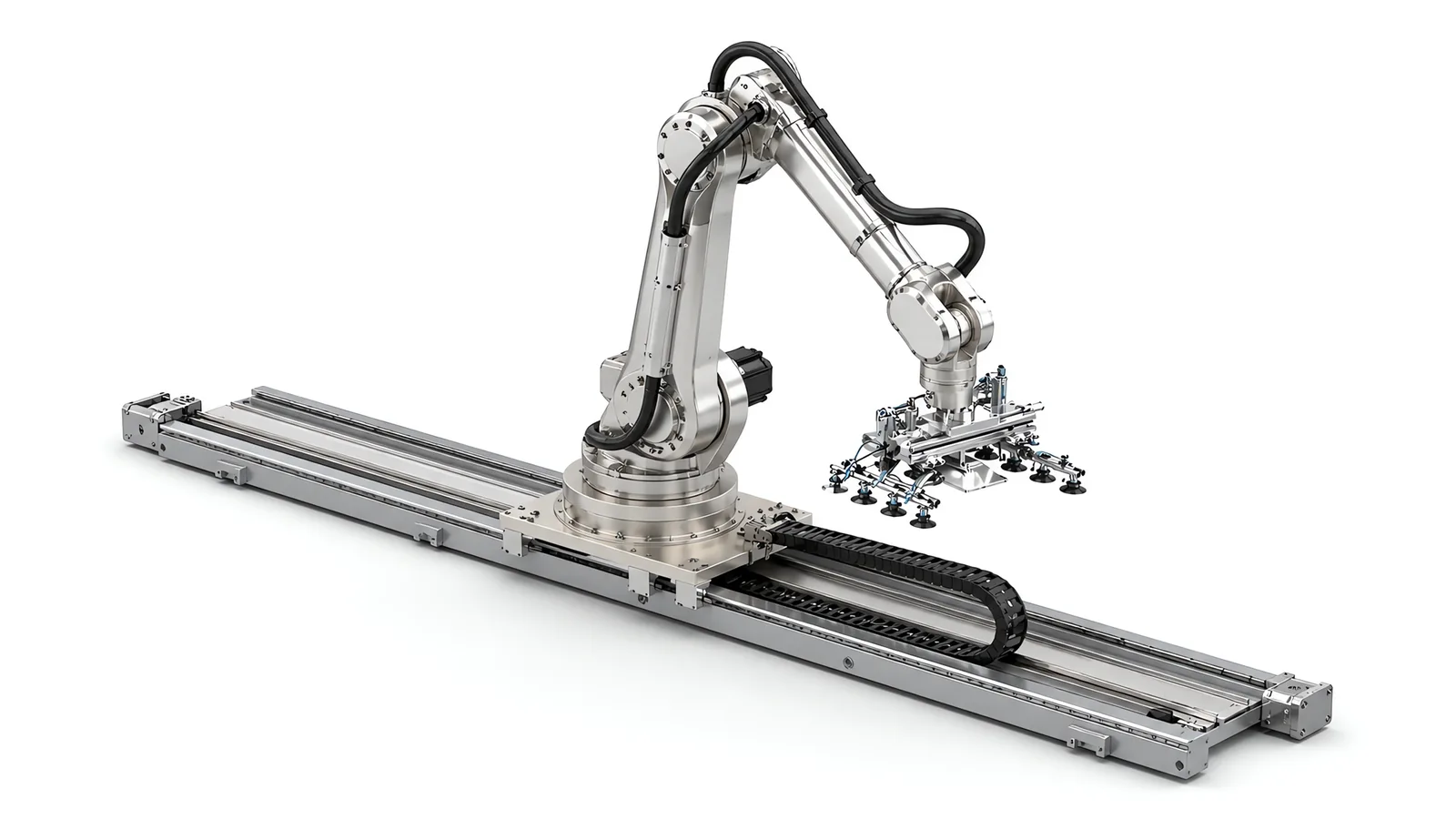
Motionwell Automation designs and builds robot linear tracks in Singapore, the seventh axis an industrial arm stands on when the work is spread out along a line. The delivered build is written up in the low profile robot track case study. Our own ultra-low-profile track is 100 mm in overall height, repeats to plus or minus 0.5 mm on a ground-grade rack and pinion, and carries a slide platform load of 1.5 tonnes, with a maximum travel speed of 500 mm/s. The delivered configuration runs 1.5 m or more of stroke on a 3 m track, bolted directly to the factory floor with no pit. Drive is a servo motor through a planetary gearbox, guidance is dual linear ball bearing rails, and the track is configured to run as a coordinated external axis on the robot controller, which is what lets carriage and arm motion overlap. Our heavy-duty robot track is the same drive architecture with the mass turned up, sized per job from a written mass budget for a large six-axis arm on a sectioned rail. What decides whether an arm fits is its base bolt pattern, its mass and moment at full extension, and whether its controller can take an external axis at all. Tracks are designed, assembled and tested at our Woodlands Link facility, and the company has delivered more than 150 special purpose machines since 2014 under ISO 9001:2015 and bizSAFE Level 3.
Overhead gantries covering a row of machines are a different machine with different economics, set out on the machine tending automation page; the wider cell scope around any arm is on our robot integration services page; the end-of-line version, where the track serves several pallet lanes, sits in the carton palletizing case study.
When Does a Robot Need a Linear Track Instead of a Bigger Robot?
Two situations, and it is worth being blunt about them because they are what reliably justifies the axis. The first is a part longer than the robot’s reach. The second is one robot that has to serve several stations which will not fit inside a single working envelope. Buying a bigger robot to cover a long part usually costs more than putting a normal robot on a track, and it does nothing for the multi-station case, because reach grows in a circle and stations sit in a line.
The distinction that decides it is spread against weight. A track answers spread: it moves the whole arm, so every point on the stroke is served by the same reach, the same payload curve and the same tooling. It does not add payload. An arm that cannot lift your part at full extension still cannot lift it after you have put it on a rail.
| Way to cover a long or spread workspace | What it buys | What it costs | Selection checks |
|---|---|---|---|
| A larger arm | Reach in every direction from one base | Higher purchase price, larger footprint, larger guarded envelope, and payload that falls away at extension | Stations in a line, because circular reach is the wrong shape for a row |
| The same arm on a linear track | Full reach and full payload repeated along the whole stroke | Floor along the track length, cabling over travel, guarding that grows with stroke, one point of failure for every station served | Work that needs weight or wrist freedom |
| A second arm on a fixed base | Independent failure, and no transit time at all | Two controllers, two tooling sets, two fenced footprints | Budget, floor area, and layouts where the second base has nowhere to stand |
| An overhead gantry | Distance built in modules, floor left clear underneath | Three axes of motion only, so the part enters as the gantry presents it | Parts that must enter an angled fixture, or a scattered layout |
For palletizing, a track lets one robot serve several pallet positions. The cycle calculation includes travel, acceleration, settling, picking and placement at each position. We compare that cycle with separate fixed robots, including the effect of a shared robot or track stopping several lanes. Buffer capacity and required lane availability help determine the best arrangement.
The fourth row is a different machine. If the machines already sit in a straight row and the parts drop vertically into them, the beam carries the distance overhead and leaves the floor clear, and the argument is made in full on the machine tending page.
What Does Track Height Cost You in Usable Working Height?
It costs you everything the track is tall. The track sits between the floor and the robot base, so the whole working envelope moves up by the track height, and that height comes out of the process end.
A conventional robot travel unit takes 200 to 400 mm of vertical working height straight out of the arm’s usable envelope. That is why our low-profile track exists: at 100 mm overall it keeps the envelope where the process needs it, and it is low enough to avoid the floor pit that tracks in this payload class often require.
| Conventional travel unit | Motionwell low-profile track | |
|---|---|---|
| Overall height above floor | 200 to 400 mm | 100 mm |
| Effect on the arm’s vertical envelope | The whole envelope rises by the track height | The same effect, but 100 mm of it |
| Floor preparation | Often a pit, to recover the lost height | Bolts directly to the factory floor |
| Consequences of a pit | Civil works, drainage, a permanent hole in the floor plan, and a cleaning problem in a clean or washdown environment | None of it |
| Platform load, delivered | Varies by product | 1.5 tonnes |
| Delivered stroke and speed | Varies by product | 3 m track, 1.5 m or more of stroke, at up to 500 mm/s |
| Repeat positioning | Varies by product | Plus or minus 0.5 mm |
Where the lost height actually bites is not obvious from a datasheet, so check these three before accepting a track height. Reaching down: can the arm still get to the bottom of a tote, a machine table or the infeed conveyor, or has the base risen far enough that the wrist bottoms out? Reaching up: raising the base helps the top of a pallet stack and hurts the ceiling clearance, and on a low-bay unit the arm at full extension is what hits the sprinkler line. And reaching in: a machine tool door or a chamber opening has a fixed height, and a pedestal in that 200 to 400 mm band can turn a straight entry into an approach angle the wrist cannot hold.
Rack and Pinion, Belt or Ballscrew on a Long Axis?
Three drives get proposed for a travelling robot base, and the length of travel settles the choice long before precision does. Our tracks use a servo motor through a planetary gearbox onto a ground-grade rack and pinion, with dual linear ball bearing rails carrying the load.
| Drive | Behaviour over long travel | Stiffness under a moving robot | Practical limits |
|---|---|---|---|
| Rack and pinion | Rack sections splice end to end, so the stroke is not limited by the drive element itself | High, and constant along the stroke because the engagement is local | Backlash at the pinion mesh has to be preloaded out, and the rack is exposed by design so it needs lubrication and protection |
| Toothed belt | A single span, so compliance grows with length and the natural frequency falls | The spring between motor and load lengthens as the carriage travels, so dynamic behaviour changes with position | Suits light, fast, shorter axes; tension is a maintenance item and stretch shows up as position error |
| Ballscrew | Length is limited by whip and critical speed, so long strokes force a larger screw and a lower speed | Very high on short strokes, which is why it belongs on Z axes and stages | The screw is the length of the travel, so it is expensive, heavy and awkward to protect over metres |
The reason rack and pinion wins on a robot track, and loses on a positioning stage, is what is riding on it. A robot on a carriage is a large mass with a moving centre of gravity, and it puts reaction torque into the axis every time the arm accelerates. That load is a stiffness problem. A drive that is compliant, or whose compliance changes as the carriage moves, gives you an axis that settles differently at each station, and that settling time is a cost you only see once the cell is running.
Two consequences belong in the specification. Because the rack splices, a stroke can be extended later by adding rack, rail and frame. And because the pinion mesh carries the load, backlash is dealt with mechanically at build time; it cannot be tuned out in software afterwards.
Why Does the Track Have to Be a Coordinated External Axis?
A track running as a separate machine turns every station change into a handshake, and those handshakes cost more cycle time than people expect.
Run as a coordinated external axis, the track servo is driven by the robot controller itself. The track appears in the same motion planner and the same coordinate frame as the arm, and track motion is planned with the arm. The arm can begin its approach while the carriage is still moving, and the controller resolves the combined path, so there are no two independent moves in series.
Whether an arm can work that way is an ordering question. External axis capability is normally a licensed option with a matching drive, it is cheap at purchase and awkward on a controller already installed, and a cell quoted on overlapped motion around an arm that cannot do it loses the cycle time twice: once at every transit, and once more in the interface somebody now has to write.
| Coordinated external axis on the robot controller | Track as an independent PLC servo axis | |
|---|---|---|
| Motion planning | Track and arm planned together, so moves overlap | Move, wait, confirm, move: the arm waits for the carriage to stop |
| Coordinate frames | One frame; a taught position includes the track position | Two frames, and positions taught per station and maintained per station |
| Programming | Robot program owns the whole motion | Robot program plus PLC axis program plus an interface between them |
| Fault handling and recovery | One controller knows where the arm and the carriage both are | Recovery logic has to reconstruct a state split across two machines |
| Offline simulation | Reach and cycle verified across the full stroke before anything is built | Simulation covers the arm; the transit is a spreadsheet estimate |
| Interface ownership | Inside one supplier’s scope | An interface, and an interface is a common place for two suppliers each to assume the other owned it |
None of this makes the PLC route wrong in every case. A track that parks at three fixed stations with long dwell at each one works perfectly well as an indexed axis. The moment transit has to hide inside the arm’s own motion, the coordinated axis is what makes it possible at all.
Either way, verify reach and cycle time in offline simulation before anything is built. A pose that cannot be reached is a mechanical problem, and on a track it is usually at one end of the stroke where nobody checked.
How Do Cables and Services Survive the Full Stroke?
Every service the robot needs has to travel with it: motor power and encoder feedback, safety circuits, fieldbus, compressed air for the tooling, and whatever the process adds. Our tracks carry them in an energy chain running along the travel with power, signal and air routed inside one managed run, under a protective cover.
Four things decide whether that installation lasts.
The first is cable specification: continuous-flex cable rated for the travel and for the chain it rides in. Rate it for the bend cycles the stroke accumulates over its life, because a track cycling a few times a minute reaches millions of bends and an ordinary jacket crazes well before that. The failure is rarely a clean break either. It is an intermittent conductor that reads as a random fieldbus dropout and gets blamed on the network for weeks. This is the same discipline that applies to the dress pack on the arm itself, covered on the end of arm tooling page.
The second is bend radius, respected at design time. A jacket cracked at a tight bend is a failure that reappears every time it is patched, and on a track it fails in the middle of the stroke where it is least accessible.
The third is fill and separation. Chain fill governs whether cables move freely or grind against each other, and power and signal want separating for noise as much as for wear. Adding a service after the chain is sized is where a well-built axis starts failing intermittently.
The fourth is where the chain lies. On a machine tending duty the chain sits in the swarf zone unless somebody routes it out of one. A carrier filling with hot chips becomes an abrasion problem long before it becomes a jam, so route it away from the chip conveyor discharge and give the chain a cover.
The track also needs travel protection independent of software: end-of-travel limit switches on the axis, so an overrun is caught by hardware.
Repeatability or Accuracy: Which Number Belongs in Your Specification?
They are different measurements, and specifying the wrong one is how a track ends up either over-bought or unable to do the job.
Repeatability describes how tightly the axis returns to a position it has already been taught. Our low-profile track repeats to plus or minus 0.5 mm through the rack and pinion drive with encoder feedback. That is a track figure: the six-axis arm riding on it holds its own, much tighter, repeatability at the wrist, and the track exists to deliver the arm to the station, where the arm does the fine positioning. Accuracy is a different claim: it describes how close the axis gets to a position it has been told to go to in a coordinate system, anywhere along the stroke. On the column palletizing track we specify plus or minus 0.5 mm positioning along the track using an absolute linear encoder, which is a positioning figure. Know which one your specification is asking for before you compare two suppliers’ numbers.
Then the harder point: neither number is placement accuracy on your part. The axis says nothing about gripper slip, part tolerance, fixture wear or thermal drift, which is usually what you end up measuring on the finished work. A long axis adds two of its own. Thermal growth accumulates with length, so a long rail in a hall whose temperature moves between the night shift and the afternoon does not hold the same absolute geometry all day. And the floor the track is bolted to is not a straight line, so the axis inherits the floor’s shape unless the levelling work removes it.
The practical answer is to stop asking the axis to be accurate and teach the process instead. Teach positions at each station, deriving nothing from a nominal track coordinate. Where a part has to be found, put a camera on it and correct the move, the approach set out on our machine vision inspection page. And match the tolerance to the part: on carton palletizing the placement tolerance is set by the carton, because the cartons themselves hold plus or minus 2 to 3 mm, and chasing tighter placement than the part holds is wasted money.
What Does the Floor Have to Do, and Do You Need a Pit?
Our low-profile track needs no pit at all. It bolts directly to the factory floor and levels on adjustable feet, six of them on our low-profile design, and that is the whole civil scope. Avoiding the pit is most of the argument for the 100 mm height: a pit means civil works, a permanent hole in the floor plan, drainage and a cleaning problem in any clean or washdown environment, and it is not something you undo when the line is rearranged.
What the floor still has to do is real work. The track is a straightedge bolted onto a surface that is not straight, so the levelling and shimming is what converts a good axis into a good installation. Three things to settle before the frame is drawn.
Flatness and level along the whole run come first, and they are measured, never assumed. A long track laid on a floor with a fall in it either gets shimmed to level or is built to follow the floor, and those are different machines. Levelling is done across the whole run at once, because correcting one foot moves its neighbours.
Anchoring has to hold the reaction loads, not only the weight. The anchors take a reaction every time the arm accelerates and every time the carriage decelerates with a robot, tooling and part on top of it. On the low-profile track that travelling mass is up to a 1.5 tonne platform load, and on a heavy-duty build it comes out of the mass budget for that job. Those are horizontal loads into the slab as well as vertical ones.
Floor loading and the route in are the third. The distributed load along the track and the point loads at the feet both need checking against the slab, particularly on an upper floor. And the track arrives in sections that have to reach the installation position through the doors and aisles that exist, which decides how the frame is split.
How Do You Protect the Track from Chips, Dust and Washdown?
Start from the fact that decides the answer: a rack and pinion axis is open by design. The pinion has to engage the rack and the bearing blocks have to engage the rails, so unlike a ballscrew inside a tube the working surfaces are not fully sealed. Protection is about keeping contamination off the engagement and getting it off again when it lands.
| Environment | What attacks the axis | What goes into the design |
|---|---|---|
| Machining swarf and coolant | Hot chips settle on the rack and are carried into the mesh; coolant washes lubricant off | Covers over rack and rails, wipers on the bearing blocks, an energy chain routed clear of the chip discharge, and a lubrication interval that assumes contamination |
| General dust and abrasive powder | Dust bridges into the grease and turns it into a grinding paste | Sealed and scraped bearing blocks, a covered rack, and a shortened relubrication interval |
| Cleanroom | The axis itself is a particle source: rack mesh, bearing recirculation and chain movement all generate | Low-particulate lubricant, covered rack, and the same chain and flex-cable specification we use on cleanroom builds |
| Washdown zones | Water and cleaning chemistry reach everything, and the cleaning agent decides the seal material | Stainless and appropriately finished surfaces, IP-rated enclosures and glands, cable runs that drain, and washdown-rated interlock switches on the guarding |
| Outdoor or unconditioned space | Temperature swing and condensation, on top of dust | Thermal growth accounted for over the length, and corrosion protection on the rack and rail |
Specify the cleaning routine before selecting enclosures, seals and guarding hardware: water pressure and temperature, cleaning chemistry, exposure duration and the surfaces being cleaned. Those conditions determine the required ingress protection, material compatibility, drainage and interlock selection across the axis.
Environment is a whole-axis design input. For a planned move from dry assembly to a wet zone, review the rack protection, lubrication, cables, drives and guarding together and include the necessary adaptations in the relocation scope.
What Does the Safety Case Look Like When the Robot Base Moves?
It grows with the stroke, and that is a cost which is easy to under-estimate. A fixed robot has one safeguarded space. A robot on a 20 m track has a safeguarded space 20 m long, plus the crushing and shearing hazards of the carriage and the track itself, which exist whether or not the arm is moving.
The method is unchanged. Start from an ISO 12100 risk assessment that determines the limits of the machine and covers every operating mode, including setup, teaching, cleaning and fault clearing, which is when guards get opened and hands go where the designer never pictured them. The robot and the integrated system are then covered by ISO 10218-1:2025 and ISO 10218-2, with each safety function rated for performance level under ISO 13849-1:2023. ISO 10218-1 was published in February 2025 as the third edition and the first substantive revision since 2011, so check which edition your contract names.
On the tracks we build, the typical safeguarding is a perimeter guard along the travel with a safety laser scanner on the load side, and reduced speed in teach mode. Four track-specific points follow from that.
Stopping distance is longer. The stopping performance that sets scanner and light curtain distances under ISO 13855 now includes the whole travelling mass, which on a heavy build is a large multiple of the arm on its own, and it gets measured on the built machine.
Safe axis limiting is worth specifying. Ask whether the arm’s safe speed, safe standstill and safe axis range limiting functions cover the track running as a coordinated external axis or only the arm. Where they do, the carriage can be restricted to part of the stroke while a person works at the far end, which changes where access points can sit without removing the guarding.
Teaching happens along the whole length. Somebody will be inside the guarded space, at reduced speed, at every station, so the access strategy has to work at all of them and not only at the near end.
And the trapping points travel. The gap between the moving carriage and anything fixed beside the track is a shearing hazard that moves along the run. It is designed out with clearance and covers at concept stage, or it is guarded forever afterwards.
Singapore does not require CE marking, but the Workplace Safety and Health Act requires dangerous parts of machinery to be securely fenced and places duties on the occupier and on anyone supplying machinery for use at work. Motionwell delivers the physical scope that follows: guard fencing and interlocked access doors, safety laser scanners, safety-rated stop circuits, and LVD and CE testing. The full method is on our machine safety and CE marking page.
How Do You Compare a Track, Gantry and Multiple Robots?
Compare the complete working envelope and production sequence using six checks.
Payload at the required reach. The arm carries the part and tooling; the track carries the arm and carriage load. Check both ratings and the arm’s load moment at every working position. Our cobot versus industrial robot comparison and robot integration services page explain the platform selection.
Travel within the cycle. Include acceleration, traverse, settling, picking and placement in the timing model. Identify which moves can overlap process dwell or pallet exchange, then verify sustained rate with the planned station sequence.
Availability by station. A shared arm and track need a coordinated recovery and maintenance plan. Buffers or independent robot cells offer ways to keep other operations producing during a station intervention.
Floor and overhead space. Compare the full guarded footprint of a floor track with the structure and service access of an overhead gantry. Our machine tending automation page shows the gantry approach.
Reach around the layout. Simulate the arm at the required carriage positions, including stations on either side, tool orientation, obstructions and service access. The result determines whether a linear axis, additional motion axes or separate robots best cover the work.
Standard travel unit or custom axis. Compare the robot vendor’s travel unit against the required stroke, carriage load, installed height and environment. A custom track addresses the dimensions and interfaces that drive your layout.
Two robots can also share a rail on independent carriages. That configuration adds coordinated travel zones, collision prevention and access protection to the design and validation plan from the start.
Standards Used in Machine Design and Validation
These references inform the design, testing and documentation described on this page. Each row links to its primary source and records the edition checked.
| Standard | Current edition | What it means for your machine |
|---|---|---|
| ISO 10218-1: Robotics, safety requirements, Part 1: industrial robots | ISO 10218-1:2025 | Published February 2025, the third edition and the first substantive revision since 2011. It adds robot classifications with matching functional safety requirements and safety-related cybersecurity requirements. Most of ISO/TS 15066:2016 on collaborative operation moved into Part 2.Checked 12 Sep 2026 against ISO 10218-1:2025 (iso.org/standard/73933.html) |
| ISO 13849-1: Safety of machinery, safety-related parts of control systems | ISO 13849-1:2023 | Provides the design method for safety-related control functions, including architecture, component reliability, diagnostic coverage and common-cause failure measures. The machine risk assessment establishes the required Performance Level; design calculations and validation provide the evidence for each function.Checked 1 Sep 2026 against ISO 10218-1:2025 normative references |
Frequently Asked Questions
Is a robot on a linear track cheaper than buying a bigger robot?
Usually, when the problem is distance. Buying a bigger arm to cover a long part normally costs more than putting a normal arm on a track, and it does nothing at all for the multi-station case, because reach grows in a circle while stations sit in a line. A track also carries a cost the bigger arm does not: it occupies floor along its whole length, the guarded area grows with the stroke, and one track fault stops every station it serves. Where a stoppage at one station cannot be allowed to stop the others, buy the second robot instead.
How much vertical working height does a seventh axis cost me?
Whatever the track is tall, because the track lifts the robot base by its own height and the arm's envelope moves up with it. A conventional robot travel unit takes 200 to 400 mm of vertical working height before the robot has done anything, which is why tracks in this payload class are often set into a floor pit to get it back. Our low-profile track is 100 mm overall and bolts directly to the floor, so the arm keeps more of its usable envelope and the civil work disappears. Check the top of your reach as well as the bottom, before you accept a track height.
Does the linear track need its own controller and PLC program?
It should not. A robot controller carrying an external axis option drives the track servo itself, so track motion is planned together with the arm. The practical difference is that the arm can start moving while the carriage is still travelling, positions are taught in one frame, and there is no move-wait-move handshake between two machines at every station. Confirm that option is on the controller before the layout depends on it, because adding it afterwards is a controller order and a re-teach. Running the track as an independent PLC axis is possible, and it costs cycle time at every transit and adds an interface someone has to own.