
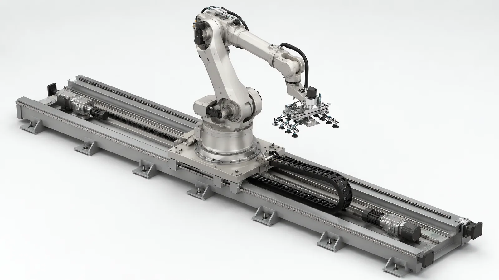
Motionwell Automation designs and builds heavy duty robot track and rail systems in Singapore, the rail a large industrial arm rides on when the work is longer than the arm is. The track we have built and delivered sits at the low profile end of that range. It is 100 mm in overall height, carries a 1.5 tonne platform load, and gives 1.5 m or more of stroke on a 3 m track at up to 500 mm/s. Repeat positioning is ±0.5 mm on a ground-grade rack and pinion, and it bolts to the floor with no pit. The build is written up in the low profile track case study. The heavy-duty class is the same engineering with the mass turned up. A servo through a planetary gearbox drives a rack and pinion, the carriage rides on linear guides, and the brake and end buffers are sized for the moving mass, specified for the arm, stroke and duty of a given job.
The carriage top plate is taken from the arm maker’s published mounting pattern, and the cable route is set by where the arm’s own dress pack exits, which is why the arm is fixed before the carriage is drawn. Machines are designed, assembled and tested at our Woodlands Link facility, and the company has delivered more than 150 special purpose machines since 2014 under ISO 9001:2015 and bizSAFE Level 3.
Arms, rails, racks, gearboxes and drives are bought as catalogue items. What we design is the frame, the carriage, the drive train sizing, the interface to your floor, the cable management, the guarding and the integration with the robot controller.
This page is about the heavy end specifically: what changes when the moving mass is large enough that the engineering changes in kind. The general case, including the reasons to put a robot on a rail at all and the 100 mm low-profile design, is on our robot seventh axis and linear track page.
What Actually Changes Above Roughly a Tonne of Moving Mass?
The concept does not change at all. A servo turns a pinion, the pinion walks along a rack, and a carriage on linear guides takes the arm to the next station. What changes is which component is the limit, and almost every limit moves off the motor and onto the structure.
There is no clean threshold, but three symptoms mark the crossing better than any number: the moving mass becomes a large multiple of the payload the arm handles, so the track is mostly moving itself; the carriage can no longer be stopped inside the guard setback the room allows; and the rail becomes long enough to be fabricated in sections.
| Design item | The light case assumes | What the heavy case forces |
|---|---|---|
| Drive sizing | Motor selected for speed and duty, gearbox for ratio | Sized on the force at the rack tooth first, then checked against RMS torque across the whole duty cycle |
| Acceleration limit | Whatever the servo delivers | Set by the rack tooth and by frame stiffness |
| Rail and frame | A stiff extrusion or a single fabricated beam | Sectioned steel, with flatness and rack pitch carried across every joint |
| Foundation | Bolt to the slab and level it | The slab is a structural component of the axis, and it is not flat |
| Thermal effects | Ignorable | Growth proportional to length, so the far end of a long rail moves against the datum end |
| Holding a stopped axis | Servo position loop holds against friction | A brake sized for the load, plus a defined sequence for who lets go first |
| Stopping | A drive ramp | An energy problem, and it sets the fence line |
| Failure consequence | A stopped station | A stopped area, because one rail can serve several stations |
Everything above the last row is engineering. The last row is availability, a business decision, and it is treated on its own further down.
What Have We Actually Delivered, and What Is a Heavy-Duty Track Specified For?
One track has been delivered, and it is the light one. The low-profile seventh axis in the table below is a built machine with a specification sheet behind every figure in its row. The heavy-duty row is a design envelope: the same drive architecture, sized per job from a mass budget and a duty profile, so every cell in it states the rule that produces the number instead of a number produced by nothing. That distinction is the first thing to ask any supplier for, because a series table with a headline load and a headline stroke does not say whether either was ever built.
| Build | Status | Platform load | Stroke | Travel speed | Repeat positioning | Drive and guide |
|---|---|---|---|---|---|---|
| Low-profile seventh axis | Delivered | 1.5 tonnes | 3 m track with 1.5 m or more of stroke in the delivered configuration | To 500 mm/s | ±0.5 mm | Servo, planetary gearbox, ground-grade rack and pinion, dual linear ball bearing rails, 100 mm profile height |
| Heavy-duty track | Design scope, specified per job | From a written mass budget: arm, base plate, dress pack, tool and heaviest workpiece | Sectioned rail, long enough to serve a row of stations | Set by stroke, duty and stopping distance | An axis repeatability figure under named test conditions, separate from tool accuracy | Servo, planetary gearbox, rack and pinion on hardened steel rails, load-rated brake and end buffers |
Two things in that table get misread in tenders.
Speed is a configuration outcome, not a class rating. The 500 mm/s on the low-profile track is the maximum the delivered configuration was commissioned to, and a heavier carriage does not automatically run slower or faster than that. What any track is finally commissioned to depends on its stroke, its duty and the stopping distance the guarding can absorb, which is why the heavy-duty row above carries a rule where a number would mislead. Ask what a track was configured for, and why.
Repeat positioning is the second, and it is not placement accuracy. ISO 9283 defines pose repeatability and pose accuracy as two different measurements with two different tests. Repeatability is the spread of the positions actually reached when the axis is sent to the same commanded point again and again, from the same direction, at the same load and under the same conditions. Accuracy is the offset between that commanded point and the mean of the positions reached. The standard is written for manipulating industrial robots, and the distinction carries straight over to the rail under one: a supplier’s repeatability figure and a buyer’s accuracy requirement can both be true and still disagree, so any track quoted with a positioning figure should say which of the two it is quoting and under what test conditions. The ±0.5 mm on the low-profile track is a repeat figure for the axis. It says nothing about where the tool ends up, which is decided by the arm, the tooling, the fixture, the thermal state and how well the station is referenced, and neither figure is what governs the process: on a palletizing cell the placement tolerance is set by the corrugated case, because the cases hold ±2 to 3 mm on their own dimensions, and chasing tighter placement than the case holds buys nothing measurable in the stack. That trade is in the palletizing robot case study.
How Do Drive Torque and Gearbox Sizing Get Decided?
They get decided by working backwards from the tooth, which is the opposite of how a catalogue is read.
The torque path is short: servo motor, planetary gearbox, pinion, rack. Motor torque times the gearbox ratio becomes torque at the pinion, and that divided by the pinion pitch radius becomes the linear force pushing the carriage. The force has to cover accelerating the whole moving mass, which is the large term, plus rolling and seal friction, plus any residual force from a rail that is not level.
Three sizing rules then apply, and two of them are easy to skip. All three run on a mass budget written down before the gearbox is picked, which is treated further down.
Size on RMS torque across the whole duty cycle, because acceleration torque is transient while heating is governed by the root mean square. A track that indexes continuously is a different thermal problem from one that makes a handful of moves a shift, at the same mass and the same profile. The same reasoning applies to every servo axis we build, and it is set out in our note on servo versus stepper motor selection.
Use the peak band deliberately. A servo will deliver short bursts well above its continuous rating, around three times continuous being a common figure on datasheets, which is exactly what a ramp needs. That headroom belongs in the acceleration budget, and a design that leans on it during the cruise phase is undersized.
Then choose the gearbox ratio for two things at once. The ratio sets the force available at the pinion and reduces reflected load inertia by the square of the ratio, which is what makes a large mass controllable by a small rotor. It also caps the top speed at the rail. Those two pull against each other, and the resolution is usually in the motion profile.
Why Does the Rack Set the Acceleration Limit Before the Motor Does?
The entire drive force is delivered into the structure through a small contact patch on a few teeth, and that patch does not care how the force was generated.
Tooth root bending and flank contact stress are the two limits, and both scale with force, which is mass times acceleration. Doubling the moving mass at the same ramp asks the same teeth to carry twice as much. A larger motor does not move that ceiling, it only reaches it sooner, and the failure is a drive fault, accelerated pinion wear, or a rack section that needs replacing under a robot.
Three responses work, and they cost different things.
The cheapest is a longer ramp, paid for in cycle time. On a track serving pallet positions, 2 to 3 seconds of transit is absorbed into the pattern cycle without touching throughput, and there a slower ramp is genuinely free. Inside a takt with no slack it is not free at all.
Next is a jerk-limited profile. Shaping the acceleration instead of stepping it cuts peak force at the same average acceleration, which buys tooth life and reduces the shock the frame sees, for a little time and some tuning.
Last is more tooth: a larger rack module, a wider face, or a second drive spreading the load across two pinions. That one is a redesign, which is why the force calculation belongs at concept stage and not at commissioning.
A fourth limit arrives with length and is not a component at all. A rail long enough to serve a row of stations is not a rigid body: drive at one end and the mass at the far end responds through the frame’s own stiffness, so achievable acceleration is limited by structural response.
What Do Rail Flatness and the Floor Have to Deliver Over a Long Span?
They have to deliver more than the floor was built to give, which is why the levelling interface is part of the machine scope. Our tracks are levelled on adjustable feet along their length, and the low-profile design bolts directly to the factory floor with no pit required. Both arrangements mean the same thing: the rail carries its own datum, and the slab only has to be strong and stable. Flatness is the machine’s problem.
That matters because an industrial slab is not flat to machine tolerance, it has joints, and it moves under load. Floor flatness and forklift traffic are already on the site-constraint list we work through on automated palletizing systems, and on a long track they graduate from a constraint to a design input. Three failure paths follow from getting it wrong.
The first is bearing blocks preloaded by the rail itself. A rail out of plane forces the carriage to bend as it travels, which raises drive friction, wears the guides unevenly and shows up as position error at one end of the stroke only. An axis that is fine at one end and drifting at the other is a geometry problem, and no amount of tuning reaches it.
The second lives at the joints between sections. A long stroke is fabricated in sections, and every joint has to carry rail flatness and rack pitch across it. That is a fabrication and alignment discipline, and it is where a track built to a drawing differs from one built to a measurement.
The third arrives after handover, as foundation drift. The pattern is familiar from robot cells generally: a system runs well through commissioning and starts missing in month three because something was nudged and the tolerance stack moved. On a track that something is a levelling foot or an anchor, so levelling checks belong in the maintenance schedule and the tool frame gets re-referenced after any foundation work, which is the tolerance-stack argument made on our robot integration services page.
What Does Thermal Growth Do to a Long Steel Rail?
It moves the far end of the axis relative to the near end by an amount proportional to length, on a daily cycle nobody is watching. Thermal growth is one of the machine-level error sources that dwarfs anything the motor contributes, alongside lead error, coupling wind-up and backlash, and repeatability lives in the mechanics generally: preload, guide quality, homing method and thermal state. On a short axis it is a footnote. On a long steel rail in a shed that is not air conditioned, it can separate a station taught in the morning from the same station in the afternoon, with drive heat at the pinion end adding to ambient along the length.
The design responses are all about deciding where the error is allowed to land.
Anchor one end and let the other float. The structure grows somewhere, and deciding where is a design choice; not deciding means the frame fights itself and the growth turns up as bearing preload instead.
Then put the datum where the tolerance is. The station needing the tightest placement belongs nearest the fixed end, because it accumulates the least growth. That costs nothing at layout stage and cannot be retrofitted afterwards.
What will not solve it is the encoder. An absolute linear encoder tells the controller where the carriage sits on the rail without a homing routine, which is worth having on its own merits, but it cannot tell the controller that the rail itself has moved relative to the station beside it. Where a station demands better than the rail holds across a temperature swing, the answer is a local feature the robot references against, or a camera measuring the real offset before the move. This is the same layering we use where an autonomous mobile robot parks to within about ±50 mm and the arm still has to reach a rack slot to a fraction of a millimetre.
How Is a Heavy Carriage Held and Stopped?
These are two problems that share a component, and conflating them is how a heavy axis ends up with a brake that holds fine and stops nothing.
| Function | What it actually does | What it must be sized on | Where it fails |
|---|---|---|---|
| Servo position loop | Holds the commanded position by injecting current against disturbance | Continuous torque at standstill | Loses the axis the moment drive power goes |
| Motor holding brake | Holds the axis mechanically when power is removed | Holding torque against the worst-case static load | Treated as a stopping device, when it was sized to hold |
| Controlled stop, category 1 | Drive decelerates the axis, then power is removed | Deceleration torque plus the time it takes | Needs the drive alive throughout the stop, which is a safety architecture question |
| Uncontrolled stop, category 0 | Power removed immediately, mechanism absorbs what is left | Kinetic energy of the whole moving mass at the speed it was doing | On a heavy carriage this is either a long coast or a hard brake application |
| Overtravel limits and end buffers | Last-resort protection at the stroke ends | Full kinetic energy at the maximum speed the axis can reach | Sized from the nominal speed |
Two consequences follow that rarely surface on a light axis.
Kinetic energy scales with the square of speed. Doubling the travel speed quadruples what a brake, a buffer or an end stop has to absorb, so a speed increase agreed late to recover cycle time is never a parameter change. It revisits the brake, the buffers and the stopping distance, and therefore the fence.
Holding a load on a stopped axis is also a sequence, not a component. If the arm is holding a case when the track stops, the brake is holding arm, tool and load together, and the release order matters: nothing moves until the system knows the pose is safe. We specify a motor brake on vertical axes, so nobody pays for continuous holding current, and that brake matters for safety when power drops. The same reasoning reaches a horizontal carriage the moment the floor is not level or the arm is extended to one side.
When Do Two Drives on One Axis Earn Their Cost?
Three different problems get solved by a second drive, and they are worth separating because only one of them is about backlash.
Force. When the required tractive force exceeds what one pinion can put into the rack at an acceptable stress, a second pinion halves the tooth loading. This is a sizing outcome.
Skew. A wide carriage on two rails wants to crab if it is driven from one side. The mechanical answer is one motor driving two pinions through a common shaft, which is what our dual-rail truss manipulators use: rack and pinion mechanisms driven through a common pivot shaft, with V-shape roller guides for dusty and harsh environments. No electronic gearing to tune, and no way for the two sides to disagree. A manipulator of that family carries several picking units on one long beam, described on our warehouse and intralogistics page, and carrying several tools is what makes the mechanical answer worth its cost there: a beam that crabs moves every pick position on it at once, so one twisted beam is a row of misses.
Backlash. Rack and pinion has lash by construction. Two servos on one rack, biased against each other so the teeth stay loaded on one flank, removes it electrically, at the cost of continuous current, heat and a tuning exercise. It is genuinely needed only where the axis positions bidirectionally to a tight band under load.
Before paying for that, check the cheaper fix: approach every station from the same direction. A single-direction approach takes most of the backlash error out for the price of a little extra travel, and on a track indexing between fixed stations it often costs nothing.
A different two-drive case is two carriages on one rail, each carrying its own robot, which is a configuration we design where two arms share a working line. Mechanically it is straightforward; the engineering moves to controls, because the envelopes overlap and an anti-collision arrangement between the carriages has to own the interlock.
How Does a Heavy Carriage Change the Safety Distance and the Guarding?
It changes them through stopping performance, which means the guarding scope is settled when the drive is sized. Miss that and the cost arrives late, after the fence has already been quoted.
Start with an ISO 12100 risk assessment driving the design. The robot and the integrated system are covered by ISO 10218-1:2025 and ISO 10218-2, with each safety function rated for performance level under ISO 13849-1:2023. The 2025 edition is the first substantive revision of ISO 10218-1 since 2011 and it references the 2023 edition of ISO 13849-1, so a design documented against the 2015 edition needs its performance level calculations restated when the machine is reassessed.
Four things then behave differently because the carriage is heavy.
The minimum distance grows. ISO 13855 sets it from the approach speed constant, taken as 2,000 mm/s up to 500 mm and 1,600 mm/s beyond, plus the stopping performance measured on the built machine and a penetration factor. Stopping performance is where mass enters the calculation, and a slower stop pushes the scanner field or the fence line outward into floor area you pay rent on.
Plain interlocking may stop being enough. Under ISO 14119, where run-down time after the stop command exceeds the time it takes to reach the hazard, the guard needs locking and not plain interlocking, released by a standstill monitor. Run-down time grows with the mass, so the heavier the carriage the easier that condition is to meet, and solenoid-locking doors are a different bill of materials from switched ones.
The stopping time itself gets measured, never calculated. Stopping performance is taken on the built cell, and it is the most important test after a control system retrofit, because a new servo drive on old mechanics changes run-down time in ways no datasheet predicts. A quotation stating a safety distance with no measurement plan behind it is stating an intention.
And the hazard is a line, not a circle. A fixed-base robot has one envelope to guard. A carriage travelling along a rail creates a moving trap against every fixed object beside it for the whole stroke, including the cable carrier trough and the fence structure itself. Reaching distances under ISO 13857 fix mesh aperture against standoff along that entire length.
One question to put to any supplier: where the arm’s controller carries safe speed monitoring, safe standstill and safe axis range limiting, ask whether those cover the track running as a coordinated external axis or only the arm. The answer changes the safety architecture, and the wider method is on our machine safety and CE marking page.
Singapore does not require CE marking, but the Workplace Safety and Health Act requires dangerous parts of machinery to be securely fenced. We deliver the physical scope that follows: guard fencing, interlocked access doors, safety laser scanners, safety-rated stop circuits, LVD and CE testing, and Ministry of Manpower lifting certification where the machine includes lifting equipment.
What Does Maintaining a Long Rack Actually Involve?
A short axis is maintained by whoever happens to be nearby. A 20 m rack is maintained by design or not at all, because no single standing position reaches it.
| Item | What it needs | What happens if it is skipped |
|---|---|---|
| Rack teeth and pinion | Lubrication delivered along the full stroke and kept on the teeth | The pinion is the wear part, and it wears into the rack it runs on |
| Linear guides | Correct preload and grease, checked at interval | Rising drive current with no change in the process, which is the early symptom |
| Debris on the rack | Covers, wipers, or mounting the rack so debris falls off it | Chips and dust turn the lubricant into grinding paste, and coolant mist strips what is left off the teeth |
| Cable carrier | Continuous-flex cable rated for the travel, on a respected bend radius | A jacket cracked at a tight bend fails again every time it is patched |
| Levelling feet and anchors | Periodic check and re-shim, then re-reference the tool frame | The month-three drift described above |
| Access along the stroke | Designed in, the way our double-beam gantries carry a maintenance walkway and railings | Maintenance that requires a scissor lift is maintenance that gets deferred |
Environment decides two of those rows. In dirty or dusty service we use V-groove roller guides, because a roller on a V edge sheds debris a ball guide would ingest, and on long-travel builds the energy chain is treated as a wear item with a replacement interval of its own, because it flexes once per stroke for the whole life of the machine.
How Does Moving Mass Get Analysed Before the Frame Is Committed?
In an order that cannot be reversed cheaply, which is why the analysis belongs in concept review. The chain runs: moving mass, then required force, then rack module and gearbox, then guide size, then frame section, then brake and buffers, then stopping performance, then the fence line and the cell footprint. Every downstream item is fixed by the one before it. Change the arm at concept review and it is a redraw; change it after the frame is fabricated and it is a new frame.
Three things belong in that analysis and are commonly missing from a quotation.
- A written mass budget at worst case: arm from the vendor datasheet, base plate, dress pack, tool, workpiece at its heaviest, and anything else riding along. Worst case, because somebody adds a heavier variant next year, and the arm is normally the dominant term in the sum.
- A duty profile, not a single move: moves per hour, distance per move and dwell at each station, across the shift pattern the line actually runs. That is what turns a peak torque into an RMS figure, and it is also where the full transit time gets counted, ramp and settle included.
- Reach verified in offline simulation before anything is built, because a pose that cannot be reached is a mechanical problem. On a track that means checking both ends of the stroke with the dress pack in place.
A supplier who quotes a track length and a payload has quoted a price and skipped the engineering.
When Is a Heavy Duty Track the Wrong Answer?
When availability matters more than utilisation. One robot on a track serving three pallet positions gives the throughput of three stations from one arm, and one failure that takes all three lanes down at once. Two robots on fixed bases fail independently. Where a stoppage on one line cannot be allowed to stop the others, buy the second robot, a trade set out in the palletizing robot case study.
When the machines are in a row and the parts drop vertically. Distance is cheap on a beam and expensive on a rail carrying an arm. A gantry travels overhead, leaves the floor clear and extends in modules, and one steel single-beam build travelling the length of a machine row services more than ten CNC machines. If parts enter a chuck vertically and the machines sit in a line, you are paying to move articulation you will not use, as our machine tending automation page sets out.
When the real problem is orientation. A track adds reach and no dexterity at all. If the part must be presented at an angle or reoriented between operations, more rail will not touch it.
When the takt has no slack. Transit absorbed into a pattern cycle is free. Transit inside a tight takt is a cycle time increase, and a heavy carriage cannot be accelerated out of it for the reasons above.
When you are past the height budget. If the constraint is that a conventional seventh axis eats 200 to 400 mm of vertical working height, the answer is the low-profile design at 100 mm, and that is covered on the robot seventh axis and linear track page.
Lead time on a build of this shape runs 16 to 24 weeks from concept approval to factory acceptance testing, which is long enough that this comparison is worth settling before the purchase order.
Standards Used in Machine Design and Validation
These references inform the design, testing and documentation described on this page. Each row links to its primary source and records the edition checked.
| Standard | Current edition | What it means for your machine |
|---|---|---|
| ISO 10218-1: Robotics, safety requirements, Part 1: industrial robots | ISO 10218-1:2025 | Published February 2025, the third edition and the first substantive revision since 2011. It adds robot classifications with matching functional safety requirements and safety-related cybersecurity requirements. Most of ISO/TS 15066:2016 on collaborative operation moved into Part 2.Checked 12 Sep 2026 against ISO 10218-1:2025 (iso.org/standard/73933.html) |
| ISO 13849-1: Safety of machinery, safety-related parts of control systems | ISO 13849-1:2023 | Provides the design method for safety-related control functions, including architecture, component reliability, diagnostic coverage and common-cause failure measures. The machine risk assessment establishes the required Performance Level; design calculations and validation provide the evidence for each function.Checked 1 Sep 2026 against ISO 10218-1:2025 normative references |
| ISO 9283: Manipulating industrial robots, performance criteria and related test methods | ISO 9283:1998 (second edition; reviewed and confirmed 2021, remains current) | Defines industrial robot pose accuracy, repeatability and their test methods. A positioning specification should identify the measured property, load, speed and test conditions so the quoted figure can be compared with the process requirement.Checked 8 Sep 2026 against ISO catalogue page iso.org/standard/22244.html (edition 2, published April 1998, confirmed 2021; ISO/TC 299) |
Frequently Asked Questions
What payload can a heavy duty robot track carry?
It carries the platform load it was sized for, and on a heavy-duty build that figure comes from a written mass budget for the job. Platform load is not the same number as robot payload and the two get confused in quotations. Platform load is everything the carriage carries: the arm itself, its base plate, the dress pack, the end-of-arm tool and the workpiece at its heaviest. On a track the arm is usually the largest term in that sum, which is why the arm has to be chosen before the track is sized. The low profile track we have delivered carries a 1.5 tonne platform load; the heavy-duty class is specified where the moving mass rises well above that.
Why is acceleration on a heavy robot track limited by the rack?
Because all the drive force passes through a few teeth. Motor torque becomes force at the pinion pitch radius, and that force is delivered into the rack across a small contact patch, so tooth root bending and flank contact stress set the ceiling. Force is mass times acceleration, so asking a heavier carriage for the same ramp asks the same teeth to carry proportionally more. A larger motor does not raise that limit, it only reaches it sooner. The usual answers are a longer ramp, a jerk-limited profile that cuts peak force at the same average acceleration, a larger rack module, or accepting a slower transit.
How does a heavy carriage change the guarding around a robot track?
Through stopping performance, which is why the guarding cost is decided at drive sizing, long before the fence is quoted. ISO 13855 sets the minimum distance from the approach speed constant, taken as 2,000 mm/s up to 500 mm and 1,600 mm/s beyond, plus the stopping performance measured on the built machine and a penetration factor. A heavier carriage takes longer to stop, so the distance grows and the fence line moves outward. ISO 14119 adds a second consequence: where run-down time after the stop command exceeds the time it takes to reach the hazard, the guard needs locking and not plain interlocking, released by a standstill monitor.