
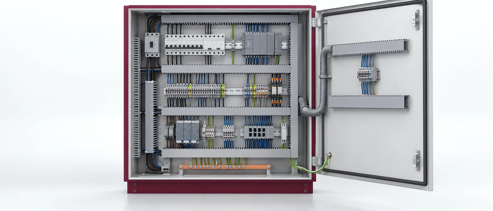
Conceptual equipment illustration.
Industrial control panel wiring should match the approved circuit design and remain identifiable during commissioning and maintenance. Start with the wiring documents and selected terminals. A neat-looking cabinet is not sufficient evidence that each circuit is correctly connected or that its field interface has been tested.
Within machine retrofit and modernization, wiring changes also need to remain aligned with the updated control logic.
Specify Each Termination Correctly
Record conductor type and size, terminal requirements, preparation and the component’s connection instructions. Ferrules are not a universal rule for every terminal technology. Phoenix Contact’s cabinet-wiring guidance describes connection technologies with different supported conductor arrangements.
Use the documented stripping and connection requirements for the selected component. If a wire or terminal changes, confirm that the preparation still suits it.
Mark wires and terminals so that the physical circuit can be traced against the drawing. Keep the as-built record consistent with the installed identifiers, including changes made during commissioning.
Define the Verification Boundary
The control-panel design and build scope includes the panel configuration. Agree which checks happen at panel completion and which require the connected machine.
| Verification stage | Evidence to retain |
|---|---|
| Assembly review | Installed devices, wiring identifiers and drawing revision |
| Circuit checks | Results required by the design and applicable equipment requirements |
| Field connection | Correct destination and cable/terminal identification |
| I/O checkout | Sensor/actuator signal observed at the intended control address |
| Sequence test | The machine responds correctly under the tested conditions |
Electrical verification must use the appropriate procedure for the installed devices; a test method suitable for passive wiring can affect connected electronics differently. Define the method and isolation boundaries in the commissioning plan.
Coordinate Panel and Site Responsibilities
A supplier may deliver a completed cabinet without installing every field cable. The electrical system-integrator scope explains how those boundaries should be named in the quotation. Identify who completes field terminations and who updates the drawings after site work.
For modified equipment, establish the relationship between old wire numbers, new terminals and revised PLC addresses. Keep temporary commissioning connections distinguishable from the finished installation.
The PLC programming scope should use the verified I/O map. A software simulation cannot establish that a field cable reaches the right terminal.
Handover a Traceable Installed System
Supply the final drawings, device configuration and relevant check records together. Labelled spare terminals are useful only when their intended status and wiring are clear in the documents.
Talk to Motionwell about the panel or retrofit to define wiring, site connection and commissioning as separate deliverables.