
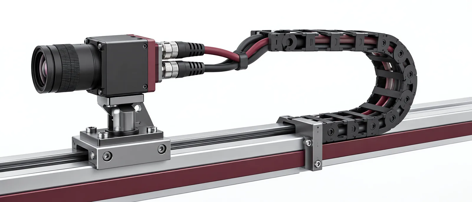
Conceptual equipment illustration.
Machine vision cables need to match both the camera interface and the movement of the machine. A cable that works on a bench can fail when it bends repeatedly, twists with a robot wrist or runs beside a switching drive. Select the exact cable assembly, including its connectors, before finalizing the camera mounting.
In a machine vision inspection installation, cable routing belongs in the equipment layout. It should not be left until the camera and enclosure positions are fixed.
Distinguish Fixed, Drag-Chain and Robot Routing
Basler’s cable range separates standard applications from mechanically demanding installations and highlights EMC, drag-chain use and connector clearance. Those requirements apply to a specific cable construction, not to every cable carrying the same interface name.
| Installation | What to check on the selected assembly |
|---|---|
| Fixed camera | Connector clearance, strain relief and permitted static bends |
| Linear moving axis | Dynamic bend radius and the manufacturer’s drag-chain test conditions |
| Robot-mounted camera | Torsion rating, wrist motion and combined bending/rotation |
| Long cable route | Supported link length, any active electronics and camera-side power |
A drag-chain declaration does not automatically establish suitability for robot torsion. Read the two ratings separately. Route enough free cable for the full motion without using a connector as the mechanical stop.
Include Power and Connector Retention
Some interfaces carry power with the image data; others need separate supply wiring. Active or optical cable assemblies can add further power requirements. Confirm these from the exact camera and cable documents.
A locking connector still needs accessible removal space and strain relief. Check the connector through the complete axis travel, including the robot position used for maintenance. A cable should not be pulled tight when the tool is parked.
Coordinate the route with the control-panel design, especially where camera data, light-trigger wiring and drive cables share the machine. Do not prescribe one shielding or earthing arrangement for all interfaces; follow the equipment’s documented scheme.
Test Transfer While the Machine Moves
Run the camera at its intended exposure, image size and acquisition rate while repeating the full axis path. Keep a record of accepted triggers, received images, link errors and unexpected camera restarts. Then repeat with the other electrical loads switching as they will in production.
A useful acceptance record identifies the cable part number, installed length, route and host controller. Swapping a bench cable for a different production assembly changes the tested configuration.
The host connection also depends on the smart-camera or PC-vision architecture. For an on-arm arrangement, our vision-guided robotics guide covers calibration and robot coordinates; a stable image link is a prerequisite for both.
Talk to Motionwell about the camera installation if the route or motion is still being decided. We can start from the layout and inspection task.