
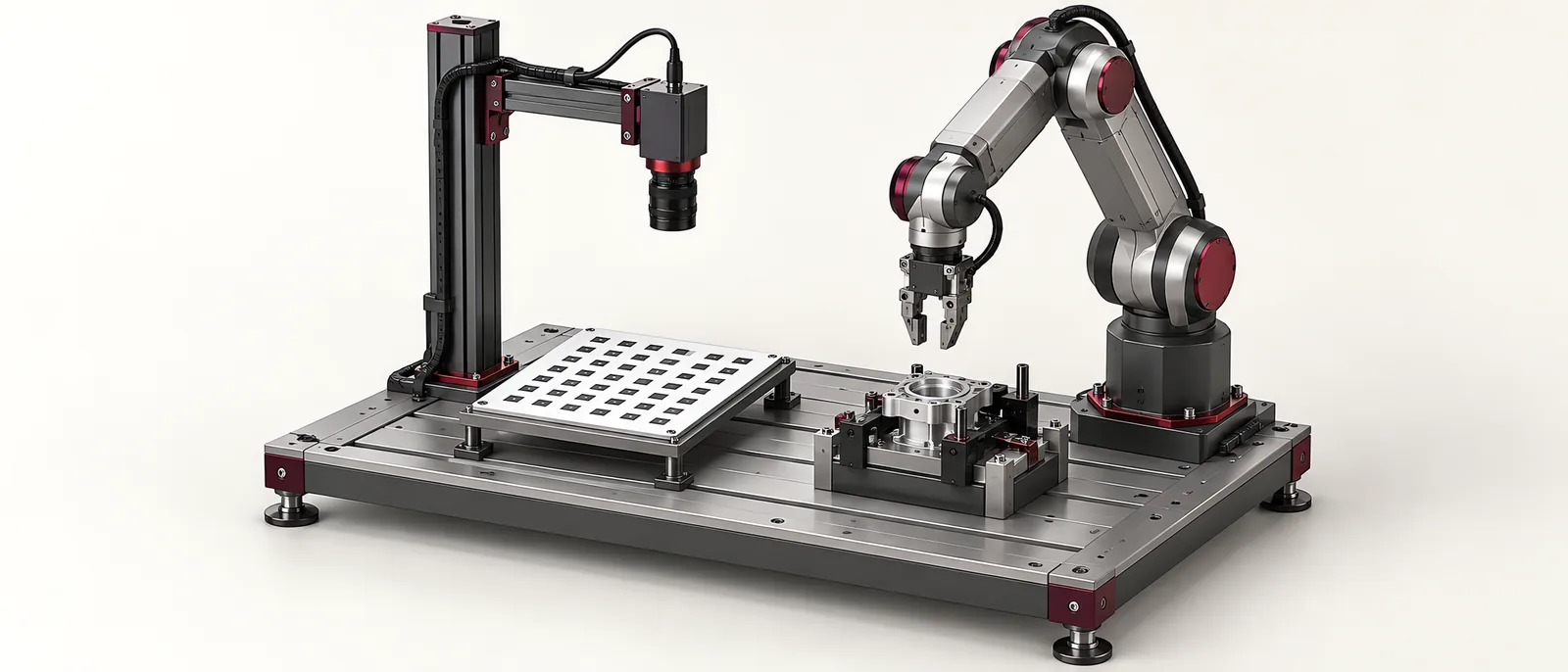
Conceptual equipment illustration.
Vision guided robotics converts an observed part location into a target that a robot can use. The difficult part is not simply finding a feature in an image. The camera result, robot coordinate system, tool position and physical workpiece must describe the same location when the motion occurs.
A reliable design therefore treats image measurement and robot positioning as one calibrated chain. It also keeps enough diagnostic information to identify where an error entered that chain.
Fixed Camera or Robot-Mounted Camera?
A fixed camera observes a defined working area while the robot moves independently. This can suit a repeatable pick zone, provided the robot and tool do not obstruct the necessary view. A robot-mounted camera moves to obtain a view, but its observation must be related to the robot pose at image capture.
Cognex’s hand-eye calibration documentation describes both arrangements and the transformation from vision measurements to robot-referenced poses. Its calibration procedure uses varied positions and orientations across the field of view. The exact acquisition requirements belong to the selected system and method.
Camera placement should follow the features that locate the part. A convenient mounting bracket is not sufficient if reflections, hidden edges or changing part height make those features unstable. The machine vision inspection scope covers the optical side of this decision.
Separate the Error Sources
| Observation | Investigate first | A useful isolation test |
|---|---|---|
| Repeated images give different coordinates | Lighting, feature selection, exposure or part motion | Capture a stationary part repeatedly |
| Image result is stable but picks have a fixed offset | Tool centre point or coordinate transform | Check a known reference with an independently verified tool |
| Centre picks work but edge picks drift | Calibration coverage, optics or working-plane assumptions | Test unused reference points across the workspace |
| Slow picks work but moving-belt picks miss | Timing, tracking and product slip | Compare stopped-belt and moving-belt trials |
| Results change after maintenance | Camera, lens, tool or fixture movement | Repeat the reference check before editing offsets |
Do not compensate several faults by adding a single programme offset. That can correct one location while worsening another.
Validate Away From the Calibration Points
Use a separate set of known positions to check the calibrated result. Include the outer operating area, different allowed orientations and the actual working heights. Record both image coordinates and robot targets so that a later problem can be traced.
For a planar 2D arrangement, establish the height range within which the mapping is valid. If the required task includes substantial height variation, evaluate the measurement method and geometry directly. Adding more 2D calibration points does not automatically provide depth information.
The part feeding and presentation design can reduce unnecessary variation. A stable presentation surface may remove a source of error before a more complex sensing method is needed.
Make Invalid Results Explicit
Define separate outcomes for a valid target, no part found, ambiguous match and a result outside the permitted working region. Attach the result to a capture or part identifier. The robot should not silently reuse the previous good target when a new image fails.
For a SCARA assembly application, also test whether the gripping and insertion process changes the relationship between the detected feature and the functional part datum. A correct visual location is only useful if the tool holds the part as expected.
Establish Recheck Triggers
Store calibration files with the camera, robot and tool configuration. Recheck after relevant mechanical changes, lens adjustment or replacement of locating hardware. A quick reference test can indicate whether the system remains within the agreed error allowance; a failed check starts a structured investigation.
Our robot integration services cover the coordination between vision, handling and machine controls. Discuss your guidance task with Motionwell.