
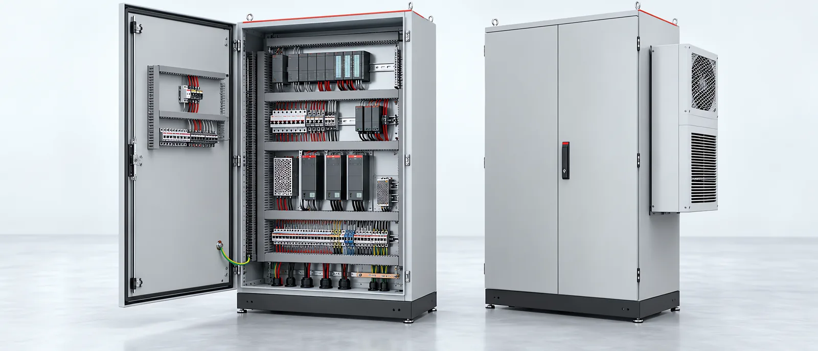
Conceptual equipment illustration.
Specify an industrial control panel enclosure from its installation environment, internal heat losses and the space needed to wire and maintain the equipment. A box that holds every component on a drawing can still leave too little room for cooling, cable bends or replacement work.
The enclosure is part of a machine retrofit and modernisation scope, while the complete electrical design belongs in the control panel design and build specification. Keep those scopes connected when comparing quotations.
Describe the Installation Environment
Record where the cabinet will stand, the ambient temperature range and the exposure to dust, moisture or process chemicals. Include the site’s cleaning method and whether access must remain possible with nearby machines operating.
Choose the required protection and materials from those conditions. Then review every opening and accessory in the proposed assembly. The cabinet body, door-mounted operator devices, cable entries and cooling equipment all form part of the installed enclosure.
Include maintenance space outside the cabinet. Check that the door can open far enough, filters can be serviced and a failed drive can be removed without dismantling adjacent equipment. These checks belong on the layout before the mounting plate is populated.
Calculate Heat Loss, Not Machine Power
Rittal’s industrial enclosure buying guide sizes thermal management from component heat dissipation, ambient conditions and enclosure properties. The power delivered to a motor is not the same as the drive’s heat loss inside the cabinet.
As an illustrative calculation, suppose two drives each dissipate 80 W at the intended duty, a power supply dissipates 30 W and the remaining installed devices dissipate 70 W:
Internal heat load = (2 × 80 W) + 30 W + 70 W = 260 W.
These assumed values illustrate the calculation. For a purchase, use manufacturer loss data for the proposed devices and duty. The 260 W total is an input to thermal selection; ambient conditions and heat transfer through the enclosure also affect the cooling capacity required.
Record assumptions about simultaneous operation and future additions. A larger mounting plate does not establish thermal capacity for additional drives.
Choose How Heat Leaves the Cabinet
Filter fans exchange air with the surrounding environment. They need suitable ambient air and a temperature difference that can carry away the heat. They cannot maintain the inside below ambient by ventilation alone.
A separated-air heat exchanger or active cooling unit addresses a different installation problem. Rittal’s climate-control overview explains separate air circuits and the role of heaters in managing condensation. Compare the available arrangements at the planned operating conditions and required temperatures.
Ask the quotation to identify the calculation conditions and the capacity at those conditions. Include airflow clearances, condensate handling where applicable, filter access and any supply or water connections the selected equipment requires.
Lay Out Service Access Before Filling Spare Space
The panel arrangement should show component clearances, wire ducts, cable bend space and access to terminals. Follow the selected equipment’s mounting requirements, including the spaces that must remain clear for airflow.
A replacement PLC or drive can occupy more room than the original. For a PLC migration and upgrade, check the installed depth and wiring route as well as the face dimensions. Confirm that the new layout still permits removal and inspection.
Agree where field cables enter and how responsibility crosses from panel fabrication to site installation. The electrical system integrator scope guide separates those interfaces so cable routing and termination are not left between quotations.
Inspect the Final Assembly, Not Only the Empty Box
Use the completed panel for acceptance checks:
| Check | Evidence to retain |
|---|---|
| Component layout and service clearances | Approved layout matched to the installed equipment |
| Cable entries and unused openings | Fitted glands, closures and the agreed protection details |
| Door and protective bonding | Drawing reference and completed electrical verification |
| Thermal arrangement | Loss calculation, operating assumptions and loaded-test record |
| Cooling maintenance | Accessible filters or service points and replacement information |
| Future additions | Space and thermal allowance tied to the planned additional equipment |
During the loaded trial, record ambient conditions, equipment duty and the measurement locations used to check temperature. Keep that record with the final drawings. It gives future modifications a starting point for checking whether the enclosure still suits the equipment inside it.
Planning a new cabinet or replacing the controls in an existing machine? Discuss the enclosure and installation scope with Motionwell.