
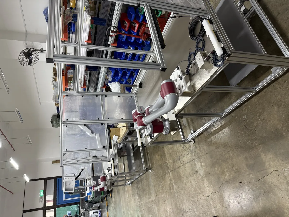
A cobot cell is judged on the whole application, and never on the arm alone. This page works through the cobot safety standards that decide that judgement: what ISO 12100, ISO 10218-1 and -2, ISO/TS 15066 and ISO 13849-1 each settle, the four collaboration modes and how to pick one, how force and pressure limits are verified on a cell that is already built, and the applications where a cobot is the wrong machine to reach for.
What Makes a Robot “Collaborative”?
“Cobot” is short for collaborative robot: an industrial robot built with safety-rated functions and a design intended for working near people. Motionwell integrates collaborative robots across medical device, electronics, and general manufacturing facilities in Singapore, including cells where the arm was already on site and had been chosen before anyone looked at the task. That second case is the instructive one, because the safety argument then has to be built around a robot nobody selected for this job, and it is where the difference below shows up first. From that work, one point is clear: “collaborative robot” describes a robot built for use around people, but safe collaboration is a property of the application.
| Term | What it actually means |
|---|---|
| Cobot as a product | The robot has built-in safety-rated functions and a design intended for human proximity |
| Collaboration as an application | The workcell, tooling, workpiece, and speeds together produce an acceptable risk level for the intended task |
ISO/TS 15066 is the reference that helps you engineer the second one. This article covers the collaborative side specifically. The wider workflow (risk assessment, performance level architecture, guarding, and CE marking for any machine) is covered on our machine safety and CE compliance page.
What Are the Safety Standards for Collaborative Robots?
Four standards apply to a collaborative robot cell at once, and each settles a different question. ISO 12100 sets the method: how hazards are identified, how risk is estimated, and in what order risk is reduced. ISO 10218-1 covers the robot arm as a product, and ISO 10218-2 covers the integrated cell, which is the machine builder’s share of the work. ISO/TS 15066 adds the collaborative part, meaning the four collaboration modes and the human contact limits. ISO 13849-1, or IEC 62061 where the safety functions are electronic, fixes how reliable each protective function has to be and how that is proven. A cobot cell is not governed by ISO/TS 15066 alone, because it is still a robot system and still a machine.
One change is worth knowing before you read the rest. ISO 10218 was revised in 2025, and most of what ISO/TS 15066:2016 said about collaborative operation now sits inside ISO 10218-2, and no longer in a separate technical specification. ISO 10218-1:2025 is the third edition and the first substantive revision since 2011, and alongside the collaborative material it adds robot classifications with matching functional safety requirements, safety-related cybersecurity requirements, and end-effector guidance. The functional safety edition moved with it: ISO 10218-1:2025 references ISO 13849-1:2023, so a cell still documented against the 2015 edition will need its performance level calculations restated when the machine is next assessed. The engineering below does not change, but if you are writing a specification or a safety file this year, check which document your contract is going to name.
| Standard | Scope | Why it matters here |
|---|---|---|
| ISO 10218-1 / ISO 10218-2 | Industrial robot and robot system integration | The baseline. A cobot cell is still a robot system. |
| ISO/TS 15066 | Collaborative operation guidance | Defines the collaboration modes and gives contact-limit guidance |
| ISO 12100 | Risk assessment methodology | How hazards are identified, estimated, and reduced |
| ISO 13849-1 (or IEC 62061) | Functional safety design | How each safety function reaches its required performance level |
If the last two are unfamiliar territory, start with the ISO 13849 and PLd design workflow and come back to the collaboration modes.
Which standards decide the guarded part of the cell?
Most production cobot cells are hybrid, so the ordinary guarding standards still govern wherever there is physical safeguarding. ISO 13857 sets the safety distances for reaching over, under, around and through openings, which is what fixes mesh aperture against standoff distance. ISO 13855 governs where a scanner or light curtain goes: the minimum distance comes from the approach speed constant K, taken as 2000 mm/s up to 500 mm and 1600 mm/s beyond, plus the measured stopping performance of the whole system and a penetration factor. That stopping term is the one that gets assumed, and it is why stopping time is measured on the built cell. ISO 14119 covers the interlocking devices and how hard each is to defeat. Where run-down time after a stop command exceeds the time it takes to reach the hazard, the guard needs locking, released by a standstill monitor.
Do these standards apply in Singapore?
CE marking is not a legal requirement for a machine installed in Singapore. The Workplace Safety and Health Act is, and it requires dangerous parts of machinery to be securely fenced, placing duties on the occupier and on anyone supplying machinery for use at work. Many multinational manufacturers here specify CE conformity as an internal standard regardless, so the ISO stack above is usually what the cell gets judged against whether or not a regulator asks for it. Where the machine ships into the EU, the European Commission’s machinery framework is what the technical file has to answer to.
What Are the Four Collaboration Modes in ISO/TS 15066?
ISO/TS 15066 describes four ways to achieve safe collaboration. There is no ranking among them. The right one depends on the task, the tooling, and how often a person is actually in the space.
| Collaboration mode | What happens | Typical fit | Typical safety functions |
|---|---|---|---|
| Safety-rated monitored stop | Robot stops when a person enters the collaborative space | Occasional human intervention, machine tending | Safety-rated sensors, stop and reset logic |
| Hand guiding | Operator guides robot motion directly | Teaching, setup, ergonomic assist | Enable device, reduced speed mode, accessible e-stop |
| Speed and separation monitoring | Robot slows or stops based on measured distance to a person | Shared area with predictable traffic | Safety scanners, zoning, dynamic speed limits |
| Power and force limiting | Robot limits impact energy in contact scenarios | Close, frequent interaction | Force and torque limits, speed limits, validated tooling design |
ISO/TS 15066 also provides guidance on body-region-specific contact thresholds and on how to measure them, which is where the verification work below comes from. Consult the current revision before you write a limit into a specification.
How do you pick a mode?
Ask how often a person is genuinely inside the space, and ask what carries the hazard. If a person enters twice a shift to reload a tray, a monitored stop is simpler, cheaper, and faster than tuning force limits. If the operator works elbow-to-elbow with the robot all shift, power and force limiting is the only mode that will not destroy the cycle time. If the hazard is the gripper or the part, no mode fixes it and you need physical safeguarding around the hazard.
How Do You Run a Cobot Risk Assessment?
The output matters more than the format. Each step below should leave a document that someone else can audit two years later.
| Step | Output you should expect |
|---|---|
| Identify hazards | A hazard list covering tooling, workpieces, pinch points and unexpected motion, and not only the robot arm |
| Estimate risk | Severity and probability assumptions written down |
| Select safeguards | Engineering controls chosen before administrative controls |
| Implement safety functions | Safety I/O map, safety PLC or relay logic, verified stop behaviour |
| Validate and document | Test records, measured limits where required, and signed evidence |
In regulated production, this evidence pack is not separate from your equipment qualification. It feeds straight into the IQ/OQ/PQ documentation for the cell.
How are the contact limits actually verified?
They are verified by measurement on the built cell, with the real tooling and the real workpiece on it. The arm’s published figures are established on the bare arm, before your gripper and your part are on it, so they cannot stand in for that measurement.
Force and pressure are two separate results. Pressure is force divided by contact area, so a gripper finger with a small radius, a part corner, or a screwdriver bit can fail a pressure limit at a force that passes with room to spare. Rounding an edge to enlarge the contact patch is often the cheapest fix available, and at concept stage it costs nothing.
Contact type changes the limit as well. Transient contact, where a person can move away, is assessed separately from quasi-static contact, where a hand is held between the moving tool and a fixed surface, and the quasi-static case is the more restrictive of the two. The layout creates that case: a bench edge, a fixture wall, a conveyor rail. Taking away the surfaces a hand can be trapped against is mechanical design work. Limits are also body-region specific, so measurement is taken where contact is credible given the arm’s reach and the operator’s posture.
Which Safety Functions Does a Cobot Cell Actually Need?
| Safety area | Typical implementation |
|---|---|
| Zone awareness | Safety scanners or interlocked doors defining speed-limited and stop zones |
| Stop architecture | System-level e-stop network, defined stop categories, safe restart rules |
| Tooling and workpiece safety | Rounded edges, limited protrusions, controlled pinch points, breakaway or compliant features where suitable |
| Verification and recovery | Vision checks, grip confirmation, and error states that prevent unsafe retries |
| Documentation | Risk assessment, safety function validation, operating instructions, training records |
Specify recovery as part of the operating task. The operator needs to know why the cell stopped, which condition must be restored and what the robot will do when restart is authorised. Test those steps with the people who will run the cell.
Recovery behaviour is specifiable, and it is worth writing down before the cell is built. On our QA laboratory system, each positioning layer retries its own tolerance check up to three times before escalating to an operator alert with the specific failure mode logged, so a transient reflection does not halt an unattended overnight run and a fault that clears itself still leaves a record. Samples run through a six-state machine whose transitions are timestamped to the millisecond, which is what keeps the audit trail intact through an error instead of breaking at it. The equivalent questions for your cell are who may clear a stop, what the robot does on restart, and whether the state it resumes into is one the records can account for.
Where Do Cobot Cells Meet Real Production?
| Delivered system | Where the cobot sits | Why the safety design is not optional |
|---|---|---|
| QA lab automation | Cobot-assisted sample handling and instrument loading, mounted on a mobile base | A shared lab needs clear zoning, predictable recovery, and traceable state transitions; see the QA lab automation case study |
| Battery module disassembly | Collaborative robot at a vision station inside a larger automated line | High-voltage workpieces mean the hazard is the part; see the battery dismantling case study |
The first of these is worth studying because the cobot rides on an AMR, which changes the safety case entirely: the collaborative space moves. Our collaborative robot applications page covers where each mode fits, and cobot vs industrial robot covers when to stop reaching for a cobot at all. If you are considering that architecture, read the AMR versus AGV selection guide alongside this page.
A third delivered cell shows how the tooling carries the safety case with it. At a consumer goods distribution centre, a cobot unloading station decants mixed SKUs from cartons into tote bins with a quick-change tool that switches between gripper and vacuum modes on its own, plus X and Y pitch adjustment on stepper motors so one tool covers several product sizes. Each tool state is a different contact geometry, so the contact assessment covers every state the tool can be in, with each one fitted on measurement day. Where floor area is the constraint we mount the arm overhead for pick-and-place and capping, which frees the floor for conveyors and operator access. That is paid for twice. Maintenance access gets harder, and an inverted mount changes the contact geometry, so approach directions and the surfaces a hand can be trapped against are reassessed, and never carried across from the bench layout the cell was proven on.
When Is a Cobot the Wrong Choice?
Cobots are oversold. These are the situations where a guarded industrial robot or a dedicated palletizing cell is the better engineering answer.
- The hazard is the payload. Assess workpiece edges, temperature and electrical energy as well as contact force. Record force in newtons and pressure against the relevant contact area; a force-limiting function does not control a hot surface or an exposed live connection.
- Cycle time dominates. Collaborative speed limits are real. If your takt time needs full robot speed, you will end up fencing the cell anyway and paying for the cobot premium for nothing.
- The tooling cannot be made safe. Long, thin, or pointed end-effectors concentrate force. Some geometries simply cannot pass a transient contact assessment.
- A person is never actually present. If the cell runs lights-out, collaboration buys you nothing and costs you throughput.
Frequently Asked Questions
| Question | Answer |
|---|---|
| If I buy a cobot, do I automatically comply with ISO/TS 15066? | No. Compliance depends on the complete application: tooling, workpiece, speeds, zones, and validation evidence. The robot is one input to the safety case. |
| How do we validate a hybrid cell? | Exercise both the guarded and shared-space phases, including the transition, stop and restart conditions between them. |
| Is power and force limiting always the best choice? | No. It suits close interaction. Speed and separation monitoring, or a monitored stop, is often better when tooling or workpiece risks dominate. |
| What mistake shows up most often in cobot safety projects? | Treating safety as a late-stage add-on. Zoning, stop architecture, and recovery logic belong in concept design. |
How Do You Implement Cobot Safety Without Losing Cycle Time?
For teams starting a cobot project, the gap between reading the standard and building a safe cell can feel large. Here is the sequence Motionwell follows during robotics integration.
First, define the collaborative task boundary. Not every motion in a workcell needs to be collaborative. In many projects the cobot runs at full speed during non-collaborative phases, such as picking from a tray with nobody nearby, and switches to a reduced-speed collaborative mode only when the operator intervenes to load or inspect. Separating those phases in the safety concept simplifies the risk assessment and stops you from limiting cycle time you never needed to limit.
Second, involve the safety assessment early in mechanical design. End-effector geometry, workpiece edges, and fixture clamping forces all drive contact severity. Across medical device and electronics assembly projects, redesigning a gripper after commissioning costs several times more than addressing it during concept review. A compliant finger tip or a rounded bracket edge can move a contact scenario from unacceptable to within the ISO/TS 15066 transient limits.
Third, plan the validation evidence from day one. Regulated industries expect documented proof that safety functions perform as designed: measured stopping distances, force and pressure readings at representative contact points, scanner zone verification. Building that test plan alongside the safety concept, never after installation, keeps the schedule predictable and avoids rework during factory acceptance. If you are still selecting a partner for this work, the system integrator evaluation framework covers what to ask about safety competency.
What Does Safe Collaboration Come Down To?
Safe human-robot collaboration is a design outcome. ISO/TS 15066 helps you choose an appropriate collaboration mode, run a structured risk assessment, and implement validated safety functions that match how people actually work in the cell.
If you are planning a collaborative robot application, contact us to review the safety concept before you lock the layout and the tooling.