
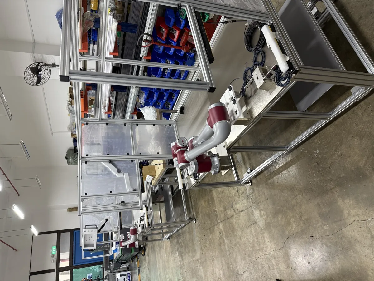
ISO/TS 15066:2016 provides guidance for collaborative industrial robot systems, including power and force limiting and human-contact limits. Much of its collaborative-operation content is incorporated into ISO 10218-2:2025. Buyers need to connect those requirements to the tool, workpiece, layout and validation evidence for their cell.
This guide focuses on that evidence: how contact scenarios are defined, what force and pressure measurements represent and what the acceptance record should contain. For an earlier-stage choice of collaboration mode, use our cobot safety standards guide. Motionwell applies these methods when building and integrating collaborative robot cells in Singapore.
The short answer. ISO/TS 15066:2016 is a technical specification, short of a full International Standard. It was written to supplement the collaborative operation clauses of the 2011 editions of ISO 10218-1 and ISO 10218-2, and it did three things those editions did not: it described what each of the four collaborative operation modes requires of the robot system, it set out power and force limiting as a design method, and it published biomechanical limits for human contact, expressed as force and pressure per body region, separately for transient and quasi-static contact. In 2025 ISO revised both parts of ISO 10218, and most of the specification’s content moved into ISO 10218-2:2025, the application and cell half of the pair. The ISO catalogue still shows ISO/TS 15066:2016 as published and under revision. For a 2025 application assessment, map the relevant requirements to supporting evidence and identify any gaps introduced by the revised text. For a buyer the consequence lands at acceptance: the collaborative measures on a cell are verified against Part 2, on the built cell, with the real tool and part, and the evidence is signed by the integrator, and no figure on the robot’s datasheet stands in for it.
The cell is the part we answer for. What each mode costs in cycle time and floor area, and when a fenced industrial arm is the better buy, are on our collaborative robot applications page.
What Is ISO/TS 15066, and Why Was It Published as a Technical Specification?
ISO publishes a technical specification when a subject is still moving and the data behind it has not settled enough for a full International Standard. The document is expected to be reviewed later, and either taken into a standard, kept as it is for a further period, or withdrawn. Collaborative operation in 2016 was that kind of subject. The 2011 editions of ISO 10218 recognised that a robot and a person could share a workspace and named the ways it could be done, but they said little about how much contact was acceptable or how a designer should prove that a contact stayed within bounds. Arms designed for contact were already on the market, and the technical specification was the way to give integrators something to design against while the standard was revised.
Reading it as a document explains its shape. Its scope is the collaborative industrial robot system and its work environment, and it says explicitly that it supplements ISO 10218-1 and ISO 10218-2. The body of the text covers the terms, the design of the collaborative robot system, the hazard identification and risk assessment that lead to a mode being chosen, and the requirements for each of the four modes. The biomechanical limit values sit in an annex presented as guidance, given per body region, and the specification itself expects them to be applied through the risk assessments. That distinction, between the requirement in the body and the guidance in the annex, rarely makes it into a purchase specification, and it matters again now that the content has moved.
| Document | What it is | What it says about collaboration | Status now |
|---|---|---|---|
| ISO/TS 15066:2016 | A technical specification supplementing ISO 10218 | The four modes in detail, the power and force limiting method, the biomechanical limit guidance | Still listed in the ISO catalogue; most of its content incorporated into ISO 10218-2:2025 |
| ISO 10218-1:2025 | The robot as a product | The safety functions a robot provides, by robot classification, that a collaborative application relies on | Current, published February 2025 |
| ISO 10218-2:2025 | The robot application and the cell | Collaborative-application requirements and validation, using the revised terminology | Current; the primary reference for a collaborative application |
| ISO 13849-1:2023 | Safety-related parts of control systems | How reliable each safety function, including the collaborative ones, has to be and how that is shown | Current; the edition ISO 10218-1:2025 references |
The documents have different roles: the technical specification records the earlier collaborative framework, Part 2 addresses the application, Part 1 supplies the robot functions, and the selected functional-safety standard supports their design. Record both the original evidence and the requirements adopted for the cell.
What Does the Collaborative Workspace Mean in ISO/TS 15066, and Why Does It Come Before the Modes?
The first thing the specification defines is not a mode but a space. The collaborative workspace is a region within the robot’s operating space where the robot system, including its workpiece, and a person can perform tasks at the same time during production. Everything else hangs off that definition. A mode is not a property of the robot, and not of the cell as a whole; it is a property of what happens inside that region, in a particular phase of the cycle, with a particular tool on the flange.
Three consequences follow, and each shows up in a safety file.
The workspace has to be drawn. A cell with a collaborative workspace has a boundary somewhere: a line on the floor, a scanner zone, a bench edge, the reach envelope of the arm under a workspace limit. The assessment has to say where it is, how it is marked, and how the robot knows whether a person is inside it. A file that names a mode without drawing the space it applies to has skipped the definition the mode depends on.
The same cell can be collaborative in one phase only. The specification treats collaborative operation as something that starts and ends. A robot can run a non-collaborative phase at full speed while nobody is in the workspace, enter a collaborative phase when a person approaches to load a part, and leave it again once the person is clear. The assessment has to cover each phase and the transition between them, including what the robot does at the moment the transition is triggered.
The space includes what is in it. The fixture, the bench, the instrument the arm is loading: each is a surface a person could be held against, and the specification’s contact categories, set out below, turn on exactly that. Defining the workspace means listing those surfaces.
Once the space is defined, the mode is a design choice made for that space and that phase, and the specification is clear that more than one may apply to one cell. That is the point at which the four modes come in.
Which Validation Evidence Does Each Collaborative Mode Need?
The 2011/2016 framework used four terms: safety-rated monitored stop, hand guiding, speed and separation monitoring, and power and force limiting. The table below uses those historical names to explain the evidence. In the 2025 editions, the capabilities are HGC, SSM and PFL; the former monitored-stop term is replaced by a Category 2 stop followed by monitored standstill. Universal Robots’ version comparison also distinguishes automatic-mode hand-guided control from freedrive used for teaching.
| Historical technique | What must be established for that technique | What that becomes at acceptance | Who holds the evidence |
|---|---|---|---|
| Safety-rated monitored stop | That the robot is at a safety-rated monitored standstill whenever a person is in the collaborative workspace, and that motion resumes only when the workspace is clear and a defined restart condition is met | A check that the robot reaches the required stop before access, that standstill is monitored, and that restart follows the assessed clearance conditions | The integrator, using a stop function the robot manufacturer declares under Part 1 |
| Hand guiding | Direct control through the specified hand-guiding device, with the enabling or hold-to-run, speed-monitoring and stopping functions required by the adopted edition | Test the permitted guiding mode, command device, speed limit and stopping functions; teaching by freedrive alone does not establish HGC | The integrator for the device and circuit, using the robot manufacturer’s supported functions |
| Speed and separation monitoring | That a protective separation distance between the robot system and a person is maintained at all times, with the robot slowing and then stopping before the distance is lost, derived from the robot’s stopping performance and the sensing system’s detection capability | Measured stopping performance on the built cell at the speeds used, sensing coverage and zone verification, and a separation distance calculated from those measurements, never from catalogue figures | The integrator |
| Power and force limiting | That contact between the robot system and a person, whether intended or incidental, stays within the biomechanical limits for the body region concerned, through the design of the robot, the tool and the workpiece and through safety-rated control functions | Force and pressure measured at each credible contact point with the real tool and part fitted, for the contact types identified in the assessment, and a record of the safety function settings that produced them | The integrator, with the robot manufacturer’s declared force and torque limiting function as an input |
Plan these tests during design and complete them on the built cell with the relevant tooling, payload and surroundings. Use the robot manufacturer’s declared functions under ISO 10218-1:2025 as inputs, and check their capability before committing to a layout.
How Does Power and Force Limiting Work in ISO/TS 15066, and What Are the Biomechanical Limits?
Power and force limiting is the mode the specification gives the most space to, and the one that gets misquoted. The premise is that contact is expected, either intended, as in a hand-over task, or incidental, as in a person reaching into the workspace. Because contact will happen, the approach is to bound the energy that can be transferred in it. The specification names two families of measure. Passive measures are in the design: rounded edges, compliant surfaces, padding, limits on moving mass. Active measures are safety-rated control functions: monitored force or torque, monitored speed, a stop when a limit is exceeded. A cell uses both, and the assessment records which of the two is carrying each contact scenario.
The biomechanical limits are the part of the document that gets quoted, and they need to be read with the qualifications the specification itself makes.
| Term in the specification | What it means | What a buyer should check |
|---|---|---|
| Body region | The limits are set per region of the body | That the assessment names which regions can credibly be reached, with no single figure applied to the whole body |
| Quasi-static contact | Contact in which a body part is held between the moving robot system and a fixed surface | That measurements were taken against the surfaces in the layout that create this case |
| Transient contact | Contact in which the body part is free to move away, so the contact is short; the specification allows it a higher threshold than the quasi-static case | That transient values were not applied where the layout makes the contact quasi-static |
| Force and pressure | Two separate limits for each region and contact type | That both were measured and both are reported, per contact point, with the tool and part that will be used in production |
| Permissible speed | The specification gives a way to turn a contact limit into a maximum robot speed for a given effective mass of the robot with its payload and a given stiffness of the body region | That any speed cap in the cell was derived for this tool and this payload, and that a heavier tool or part gets a new derivation |
Two qualifications sit behind that table. The values were published as guidance in an annex, while the requirement in the body of the text was that the risk assessment set the limit for each contact, applied to the body region concerned and verified by measurement on the built cell. And they belong to the application, because the effective mass and the contact geometry are set by the tool and the workpiece the integrator fits. A robot manufacturer can and does test the bare arm against them; that test tells you the arm can be limited, and nothing about whether your cell is.
Why the pressure result and the force result diverge on a real tool, and what that forces on gripper geometry, is worked through on our collaborative robot applications page, with the grip-security side of the same trade-off on our end of arm tooling design page.
How Are the Biomechanical Limits Measured on a Built Cell?
Use calibrated force and pressure measurement equipment with contact characteristics suited to the assessed body region. Record the mounting, compliance, approach, speed, tool and payload in the test method. Pressure film or a suitable pressure sensor supplies information the robot’s torque estimate cannot. The mounting and collision simulation follow the validated test method; transient contact does not require a freely moving instrument in every test configuration. The DGUV instrument study identifies mounting rigidity as a factor in repeatable results.
The method has consequences that turn into line items in a quotation.
- Each credible contact point is a separate measurement. The assessment lists the points where a person can be contacted given the layout and the task, and the measurement campaign follows that list.
- The approach direction matters. A gripper finger arriving edge-on and the same finger arriving flat are different contact areas and therefore different pressures. The direction measured is the direction the assessment says the contact would occur in.
- The result belongs to a parameter set. Force limiting, speed caps and workspace limits on the controller are settings, and the measurement is evidence for the settings in force when it was taken. Change a setting and the affected measurements are repeated.
- Every tool state is a separate geometry. A quick-change tool, a gripper with adjustable pitch or a head that switches between gripping and vacuum presents a different contact shape in each state, and a measurement taken on whichever state was fitted that day covers that state only.
- The robot’s own readout is a design aid. The controller’s force and torque estimate is what the safety function acts on, and it is useful for tuning before the campaign. It is not what the limit is compared against, because it does not measure pressure and does not know the contact area.
Where the measured pressure fails and the force passes, the fix is on the tool. Where both fail, the options are a lower speed cap for that phase, a lighter tool or part, or a redesign that removes the contact scenario, and the choice between them is a cycle time decision as much as a safety one. What each of those costs against the rest of a cell is the subject of our guide to what drives the cost of an industrial robot cell.
What Changed When ISO/TS 15066 Was Incorporated into ISO 10218-2:2025?
Compare the adopted requirements with the existing application assessment, design and test evidence. This identifies whether the update changes a safety measure, a validation test or the documentation. Our guide to the ISO 10218 robot safety standard covers the wider robot classifications, cybersecurity and end-effector requirements; the table below focuses on collaboration.
| Item | Under ISO/TS 15066:2016 | Under ISO 10218-2:2025 | What to do about it |
|---|---|---|---|
| Document status | A technical specification supplementing the 2011 editions | Part of the application standard itself | Use the adopted Part 2 requirements and identify supporting TS references and edition differences |
| The four historical techniques | Defined in the 2011/2016 framework | HGC, SSM and PFL capabilities; Category 2 stop with monitored standstill replaces the former monitored-stop term | Map the selected technique to the current functions and terminology, then review its implementation |
| Power and force limiting | The design method and its two families of measure | Carried into Part 2 | Review the contact scenarios, limiting measures and validation against the adopted requirements; update the design where a gap exists |
| Biomechanical limits | Guidance values in an annex | Carried into Part 2 | Check the Part 2 text for how the values are presented before quoting them in a specification; do not assume the annex status carried over unchanged |
| Robot safety functions relied on | Referenced to the 2011 edition of Part 1 | Declared under ISO 10218-1:2025 by robot classification | Ask which classification the arm’s declaration names and get the safety function specification that goes with it |
| Functional safety of those functions | ISO 13849-1:2015 where the file was written before the 2023 edition | ISO 13849-1:2023, the edition Part 1 now references | Review the affected function requirements, calculations and validation against the adopted edition |
| What “most” leaves out | Everything in the specification | Not necessarily everything, or not in the same form | Where a file depends on a particular clause of the specification, look up its counterpart in Part 2 before assuming one exists |
For an earlier robot, retain the manufacturer’s declaration and test reports with their original editions. Check whether its declared functions support the planned application, then map the existing evidence to the adopted Part 2 requirements. A purchase order can specify the required editions and documentation; confirm availability and conformity with the supplier against those requirements.
What Does the Incorporation Mean for Accepting a Collaborative Robot Cell?
Acceptance is where the incorporation stops being a citation question. A collaborative cell is accepted in two events, factory acceptance on the builder’s floor and site acceptance in the plant, and the collaborative evidence is split between them in a way that follows from the specification’s own logic: whatever depends only on the cell can be measured at the factory, and whatever depends on the plant’s people, surfaces and traffic has to be repeated on site. Our general test structure is on the factory acceptance test checklist; the items below are the collaborative additions to it.
| Evidence item | Belongs to | Produced at | What it has to show |
|---|---|---|---|
| Risk assessment naming the collaborative workspace, each phase of the cycle and the mode applied in each | All modes | Design, before build | That the space is drawn, the phases are listed and the transitions are covered, under the method of ISO 12100 as applied by Part 2 |
| Robot declaration and safety function specification | All modes | Before build, from the robot manufacturer | The Part 1 edition, the robot classification, and each safety function the cell relies on with its declared level |
| Stop and restart demonstration | Safety-rated monitored stop | Factory acceptance, repeated on site | The required stop is achieved before access; monitored standstill and restart conditions are demonstrated |
| Enabling device and guided speed test | Hand guiding | Factory acceptance | Each enabling state behaves as specified; the guided speed limit holds; the stop is reachable from the guiding position |
| Stopping performance measurement | Speed and separation monitoring | Factory acceptance, confirmed on site with the final layout | Stopping distance and time at the speeds used, with the tool and payload fitted |
| Separation distance and zone geometry | Speed and separation monitoring | After the measurement above | A distance derived from the measured stopping performance and the sensing system’s detection capability, and the zones that implement it |
| Contact force and pressure records | Power and force limiting | Factory acceptance, repeated on site where the surroundings differ | Force and pressure at each credible contact point, the applicable contact types and assessed tool states |
| Safety configuration record | All modes | Factory acceptance, re-issued after any change | The version of the robot’s safety parameters that produced the results above, and who may change it |
| Performance level calculations | All modes | Design, confirmed at factory acceptance | Each cell safety function rated under ISO 13849-1:2023, matched to the levels the robot’s functions were declared at |
Three things about that list are easy to get wrong in a contract.
The measurements need the production tool and part. A factory acceptance run with a lighter demonstration part, or with a gripper that has not yet had its production fingers fitted, produces contact and stopping figures for a cell that will not exist on site. Where the production part is not available at factory acceptance, the contract should say which measurements are provisional and when they are repeated.
Confirm site-dependent conditions. Nearby surfaces, traffic through scanner zones and the operator’s task may differ from the factory setup. Check the final arrangement and repeat the affected stopping, separation or contact tests.
The record has to survive the next tool. A change to the tool’s mass or geometry reopens every contact scenario that tool takes part in, and a new product variant usually arrives as exactly that kind of change. Assessing the tool family as an envelope of mass, reach and geometry at the start is cheaper than a per-variant measurement campaign discovered at the second product. Scoping that reassessment so that it is bounded is the subject of our guide to machine safety risk assessment.
The assessment may call for changes to the tool, layout, safeguarding or robot functions. Whether a collaborative arm or a fenced industrial robot was the right purchase in the first place is a separate question, answered on our guide to what a cobot is for the definitions and on our cobot vs industrial robot comparison for the decision. The evidence above is what a correctly chosen collaborative cell is accepted on, and the earlier treatment on our cobot safety standards page still describes the engineering behind it accurately.
Where Does ISO/TS 15066 Stand Now?
ISO/TS 15066 remains useful for understanding the earlier collaborative framework. For a new application using ISO 10218-2:2025, map that material to the adopted requirements and terminology. Keep the cell assessment, contact or separation evidence and safety-parameter version linked, so an equipment change can be reviewed against the conditions actually validated.