
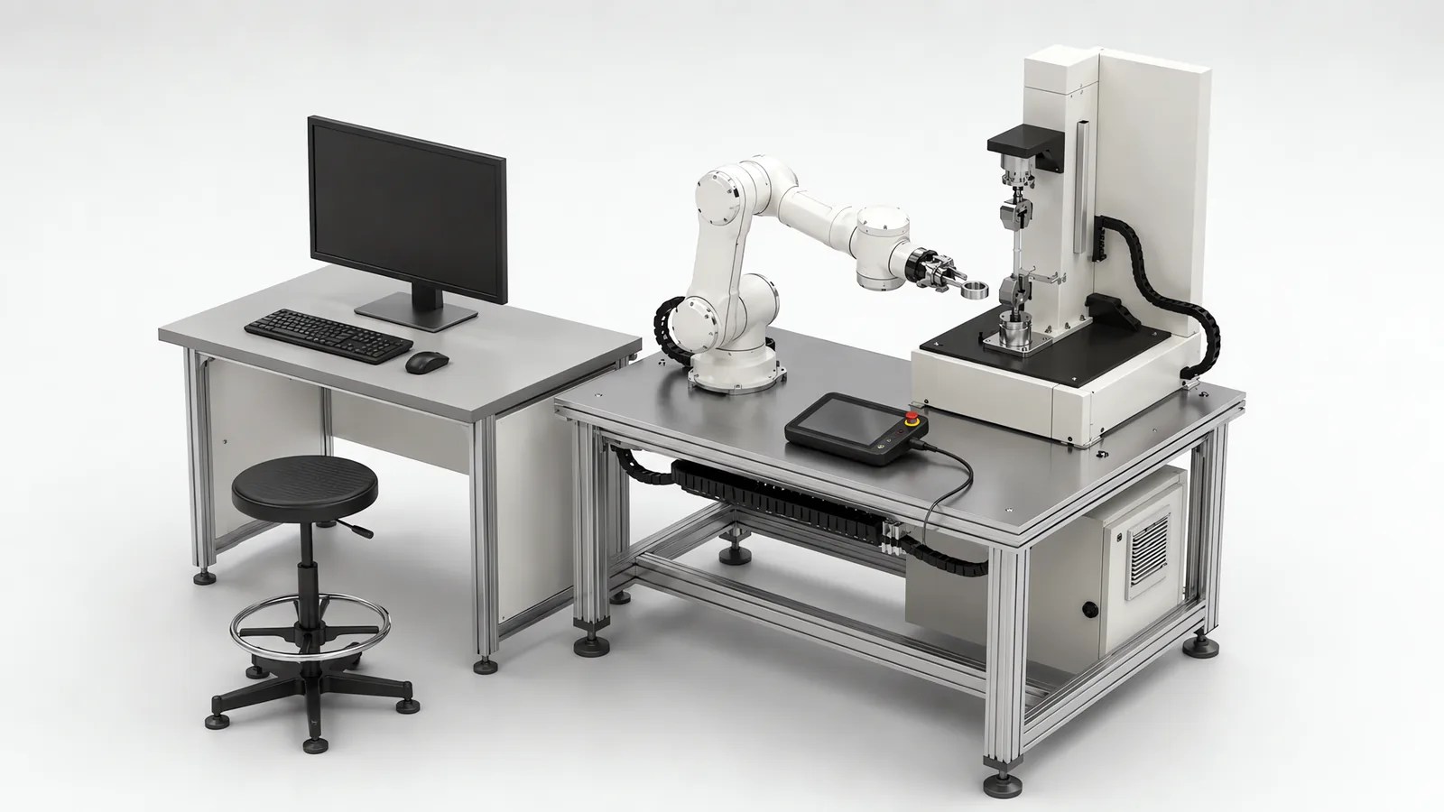
A cobot, short for collaborative robot, is an industrial robot equipped with functions intended to support work near people. Those functions can include safety-related speed, position, stop and force limits. The complete application determines how people and robot may share the workspace, including the effects of the tool, part and fixtures.
Motionwell integrates collaborative arms in Singapore for laboratory instrument loading and cleanroom automated testing. This guide explains the definition, common forms of human interaction and the safety functions used through a cycle. The equipment scope is on our collaborative robot applications page.
The arm-against-arm comparison on speed, payload, reach, guarding and whole-cell cost is on our cobot vs industrial robot page. This guide focuses on the definition and the forms of human interaction behind a collaborative application.
What Does the Word Cobot Actually Mean?
The name describes the intended use, not a fixed size, payload or geometry. Many cobots are articulated arms; our types of industrial robots guide separates motion geometry from collaborative safety features. Compare the actual model’s functions and limits instead of treating the label as a complete specification.
The term the standards build on is collaborative operation, which is something an application does. Since the 2025 revision that subject sits in ISO 10218-2:2025, the part of the robot safety standard that governs industrial robot applications and robot cells. The robot itself, as a product leaving its manufacturer’s factory, answers to ISO 10218-1:2025, which now ties functional safety requirements to a classification of the robot and adds end-effector guidance. Much of ISO/TS 15066:2016 was incorporated into the revised robot and application standards. The familiar four-technique terminology needs an edition check: the 2025 framework uses hand-guided controls, speed and separation monitoring, and power and force limiting as collaborative capabilities, with monitored standstill treated as a safety function. What that reshuffle changes for a cell buyer is on our guide to the ISO 10218 robot safety standard, and how the contact limits are verified on a built cell is on our ISO/TS 15066 guide.
The product and application assessments answer different questions. The table follows the information needed from robot selection through cell validation.
| Where the word appears | What it refers to | Who decides it | What stands behind it |
|---|---|---|---|
| In the catalogue | An arm sold with safety-rated functions for use near people | The robot manufacturer | The manufacturer’s declaration under ISO 10218-1, with its robot classification |
| In the layout review | An application in which a person and the robot are intended to share space during the cycle | The buyer and the integrator together | A description of who is in the space, when, and doing what |
| In the risk assessment | A verdict that the application, with its tool, part, fixture and people, reaches an acceptable risk | The integrator, documented against ISO 10218-2 | Hazard identification, the mode chosen for each moment of the cycle, and the safeguarding that remains |
| In the safety file | A cell whose collaborative modes have been validated on the built machine | Whoever signs the validation | Measured stopping performance, measured forces and pressures where contact is permitted, and a record of who may change safety settings |
The manufacturer’s data supports the later design stages. The buyer and integrator add the process, workpiece, layout and access information needed to assess the complete cell.
What Makes a Cobot Application Safe?
Safety functions provide design options; the risk assessment determines how to use them. An assessed robot is not automatically a cobot, because conventional industrial robot cells also require assessment.
Start with the manufacturer’s specified load limits, stopping information and safety-function performance. Add the actual gripper, workpiece edges and temperature, fixture pinch points and access by operators or visitors. Those details determine the hazards and the protective measures needed around the robot.
So the arm’s certification is a statement about the arm, and the collaborative verdict is a statement about the cell. Between the two sits the risk assessment, run the same way as for any other machine: hazards identified, risk estimated, risk reduced in the ISO 12100 order of inherently safe design, then safeguarding, then information for use. The method is on our guide to machine safety risk assessment, and the workflow that turns it into a signed safety file is on our machine safety and CE marking page. What a cobot changes in that assessment is one thing. It adds collaborative operation to the list of risk-reduction options the assessor can choose from. It removes nothing from the list of hazards.
That framing explains the outcome that surprises buyers: a cell built around a collaborative arm that ends up partly guarded. The assessor found a hazard the arm’s functions do not touch, a sharp workpiece or a pinch point against a fixture, and safeguarded it physically while leaving the shared loading station open. The result is a hybrid cell, which is a normal outcome and not a failure of the technology, and the four kinds of hazard that produce it are set out on our collaborative robot applications page.
One consequence for how you write a specification. “A collaborative robot shall be used so that no guarding is required” is a line that appears in requirement documents, and it puts the conclusion of the assessment into the input of the assessment. Write instead who needs to be where during the cycle and what they do there, and let the assessment decide what that requires. The rest of that discipline is in our guide to writing an automation URS.
Is Sharing a Space the Same as Sharing a Task?
No, and the word collaborative hides the difference. The following interaction patterns help describe who shares the space and when. They are practical process descriptions, not safety-standard classifications.
| Level | Where the person is | What the robot does when the person is near | How it is usually handled |
|---|---|---|---|
| Separated | Outside a fence, entering only when the robot is stopped and isolated | Nothing changes, because nobody can reach it while it runs | A conventional guarded cell. Not collaborative |
| Coexistence | In the same room, on a different task, with no fence between them | Slows or stops as the person approaches, then resumes | Separation monitoring or a monitored stop, with a scanner watching the approach |
| Sequential cooperation | At the same station, taking turns: the person loads a fixture, steps back, the robot takes over | Holds still while the person is at the station, works when they are not | A monitored stop at the handover, with the station designed so the two never need to move at once |
| Simultaneous interaction | Person and robot work in shared space; they may or may not handle the same part | Motion follows the validated contact or separation conditions | Power and force limiting where contact is permitted, or separation monitoring where contact is prevented |
The delivered laboratory and cleanroom examples below involve people working around loading and testing tasks. The selected protective arrangement depends on each access point and operating phase; the interaction table is a design aid, not a statement of their measured safety settings.
Power and force limiting can address credible incidental contact even when the person and robot do not handle the same part. Assess each contact location, body region, trapping possibility and tool shape. Alternatively, a monitored-separation design prevents contact by maintaining distance or stopping. Choose the protection from the actual interaction and hazards, not from whether the task is described as shared.
Deciding the row is a question about your process, not about robots, and it is the first thing to settle. It fixes which modes are available, how much floor the cell needs, and whether the cycle time you want is reachable at all.
How Do the Four Collaborative Modes Play Out Inside One Cycle?
The familiar four-technique description covers monitored stop, hand guiding, speed and separation monitoring, and power and force limiting. Under the 2025 terminology, monitored standstill is a safety function supporting the application. A cell may combine supported techniques across its operating phases; it does not need to use all four. Universal Robots’ safety-function guide explains the terminology change and distinguishes hand-guided teaching from hand-guided operation. What each mode needs in hardware and what it costs in throughput is tabulated on the collaborative robot applications page. The table below follows one illustrative laboratory tending cycle instead.
| Moment in the cycle | Who is where | Mode in force | What the safety system has to know |
|---|---|---|---|
| The arm moves specimens between a rack and an instrument with nobody nearby | Technicians elsewhere in the room | Speed and separation monitoring | Where the nearest person is, from a safety-rated scanner, and how far the arm travels before it stops at its current speed |
| A technician walks past to reach a bench behind the cell | Inside the scanner’s warning zone, away from the station | Speed and separation monitoring, at reduced speed | The separation distance that must hold at the reduced speed, so the arm can stop before contact if the person keeps coming |
| The technician stops at the station to reload the rack | At the station, hands inside the shared space | Safety-rated monitored stop | That the arm is at standstill, that the standstill is monitored, and the conditions under which it may restart once the space is clear |
| An operator guides a supported handling movement | Holding the approved guiding device | Hand-guided controls | Guiding controls, enabling or hold-to-run requirements, speed limits and stop functions specified for the application |
| The technician steadies a fragile specimen while the arm seats it | Hands on the same part as the gripper | Power and force limiting | The measured force and pressure at each credible contact point with this tool and this part, against the limit for the body region that could be struck |
The last row illustrates one use of power and force limiting. Other cells use it for incidental contact in shared space. A tending task can instead keep contact out of the permitted operating conditions through separation monitoring and controlled handovers.
Three things follow from reading the modes as states.
First, specify the protective conditions for each phase. Power-and-force-limited motion must meet the assessed contact limits. Separation-monitored motion can use a different speed when distance permits, within the robot and application limits. Validate how the safety system changes between those conditions.
Second, identify the safety functions that enforce each operating condition and transition. Determine their required performance and validate the complete implementation, including any external sensing. Standstill has to be proven monitored, the stopping distance measured, the restart conditions exercised, and where contact is permitted the forces measured with the real tool and part. That evidence is generated during acceptance testing, which is why safety functions appear on our factory acceptance test checklist as items to be demonstrated one at a time, never as a single line saying the cell is safe.
Third, select by available functions. An industrial arm with suitable safety-related stop and speed functions can form part of a monitored-stop or separation-monitored application, with the required presence sensing. For power and force limiting, evaluate the robot’s design, control functions and measured contact behaviour with the actual tool and load. The cobot vs industrial robot comparison includes these architecture choices.
What Do Buyers Commonly Get Wrong About Cobots?
Seven misconceptions arrive with the word, and each costs money at a predictable point in a project.
| What gets assumed | What is actually the case | Where the cost lands |
|---|---|---|
| A cobot is a safer robot | It is a robot with safety functions that make a safer application possible. The safety belongs to the cell and is produced by the assessment | The assessment is shortened, and the missing hazard is found at validation or by an auditor |
| A cobot needs no fence | Guarding is decided by the assessment. A hazard in the tool or the part is safeguarded physically whatever the arm can do | A fence is added after the layout is frozen, into floor that was never allowed for it |
| A cobot is a small or light robot | Payload and reach vary by model. Heavy or sharp loads affect the permitted interaction and may need separation or guarding | Load-related protection is added late if the workpiece was omitted from the assessment |
| A cobot is slow | Speed depends on the model, load and configured protective functions. Separation monitoring can permit a faster phase when distance allows, then reduce speed or stop as someone approaches | A cobot is rejected for a task it could have made rate on, or bought for one it cannot |
| A cobot is easy to program, so no integration is needed | Hand guiding teaches points quickly. The tooling, the part presentation, the fixtures, the controls, the safeguarding and the validation evidence are the cell, and the arm is one bought component inside it | The arm arrives and waits for the cell nobody scoped |
| A cobot senses the people around it | Do not assume the arm locates people. Check which presence-sensing functions the model provides; separation-monitored applications commonly use safety-rated scanners or other protective equipment connected to the safety controller | A cell laid out with no room for a scanner zone, so separation monitoring is unavailable and the whole cycle drops to contact-limited speed |
| A cobot works beside a person on the same part all shift | That is the simultaneous case, the one with the heaviest assessment burden. Many cells are collaborative for a few seconds per cycle at a handover and run at application speed the rest of the time | The whole cycle is designed to the speed cap of a moment that lasts seconds |
Two of those rows deserve a paragraph.
Compare cycle time in the configured application. A cobot is not necessarily held to one contact-limited speed while unattended; supported safety functions may permit a faster phase with adequate separation. The model’s maximum performance, load and process dwell still apply. Record how often someone approaches and include the resulting slowdowns or stops in the sustained-rate test.
The programming row is the one that produces the arm in the crate. Hand guiding and a tablet interface make teaching a point fast, and the demonstration is persuasive. What the demonstration does not show is everything a taught point depends on. A part that arrives in an arbitrary pose needs vision and fixturing before the arm can pick it. An instrument with no accessible control interface needs engineering before the arm can load it. A rack that a technician nudged needs a reference the arm can find. What an integrator supplies around an arm, and where the brand of the arm gets decided, is on our robot integration services page.
What Do Two Delivered Cobot Cells Show About the Definition?
Two delivered cells make the definition concrete, and each answers a different half of it.
The QA laboratory automation programme pairs a collaborative arm with an autonomous mobile robot: the vehicle carries samples between storage and the test instruments, and the arm loads and unloads each instrument at the station. Why that laboratory could not simply be fenced is argued in full on the cobot vs industrial robot page, under shared space that cannot be divided. What the project adds to the definition is the separation between two decisions that the word cobot fuses together. Who is in the space decided that the application had to be collaborative. What could load an instrument from a docked vehicle decided that the handling device was an arm. Neither answer contains the other. What a moving collaborative space does to the assessment is set out on the cobot applications page. The wider architecture around the arm, including scheduling and traceability, is on our laboratory automation page.
The cleanroom automated test equipment answers the other half, about what a collaborative arm can do when it is chosen for the right reason. The arm loads and unloads specimens at the fixture interface, with located handling and specimen-linked test records. The loading arrangement combines the robot, fixtures, enclosure openings and operator access in one assessment. Reprogrammable loading supports product variation, while the final safeguarding and test method follow the application; the general form of that argument is in our guide to reducing changeover time. What the project shows is that precision and collaboration are not in tension, and that the reason to buy the collaborative arm was the variety of the work and not the presence of a person.
Put the two together and the definition holds. In one cell the person decided the mode and the task decided the arm. In the other, loading flexibility, fixture location and access protection work together. In neither did the word cobot on the purchase order settle anything by itself.
When Is a Cobot the Wrong Starting Point?
The arm-against-arm cases, where a fenced industrial robot is the better machine because the payload is the hazard, the cycle time needs full speed, the tooling cannot pass a contact assessment or the reach is out of band, are worked through on the cobot vs industrial robot page. The cases below are different. They are the ones where a cobot is the wrong place to begin the conversation, whatever the alternative arm would have been.
The access requirement is unclear. Describe who needs to enter, for which task and at which point in the cycle. Include assessment and validation in the delivery scope, with contact measurement where the selected design requires it.
The motion is fixed and the rate is high. A part that always arrives in the same place, always goes to the same place and never changes shape is a pick-and-place mechanism or a gantry, and an articulated arm of any kind is paying for freedom the task does not use. Where a gantry beats an arm for machine tending, and where it does not, is on our gantry vs six-axis comparison.
The problem is upstream of the station. A manual station is often slow for reasons a robot inherits: parts arriving unsorted, an instrument that has to be driven through its own menus, a changeover that takes the morning. Automating the hand motion leaves the wait in place. Measuring where the time goes before choosing what to automate is the subject of our guide to improving production efficiency.
The budget was set from the arm’s price. A collaborative arm is a bought component, and the cell around it is the project. Where the money goes in a robot cell, and why two cells built around the same arm can be priced far apart, is on our guide to industrial robot cost drivers.
The tool introduces a contact hazard. A pointed, protruding or hot tool can require separation or localized guarding even with a collaborative arm. Start from the end-of-arm tooling design and identify where people can safely load, observe or recover the process.
So What Is a Cobot, in One Sentence?
A cobot is an industrial robot equipped to support collaborative applications; safe collaborative operation depends on the complete cell design and validation. Specify the task and human access first, then compare the robot, tool and protective functions against the required production rate.