
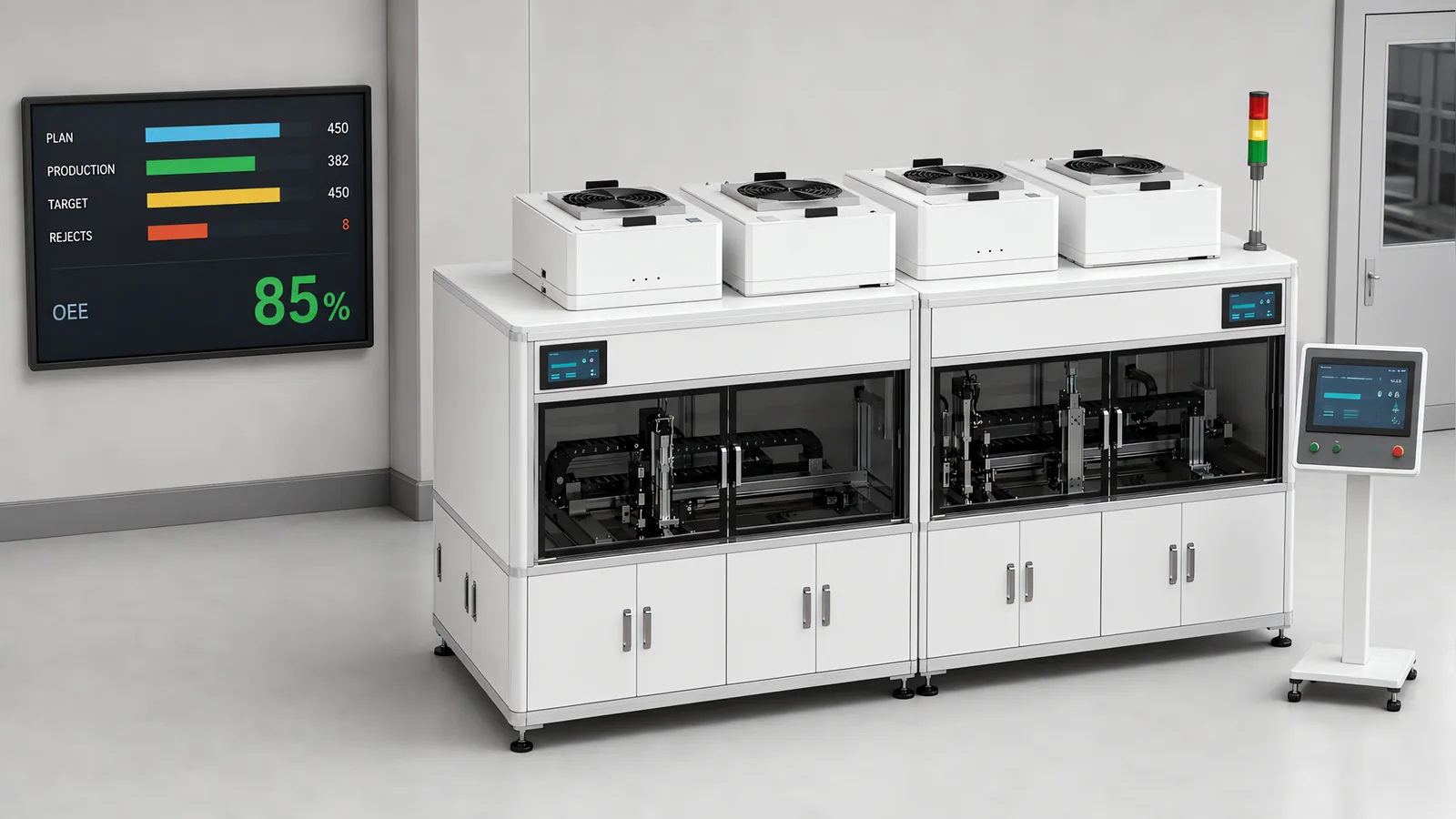
To improve production efficiency, find the loss that limits good output: a slow operation, repeated stops, long changeovers or a station waiting for material. Measure that loss on representative products before selecting a software change, feeder modification, station redesign or control retrofit.
Motionwell builds custom machines and modernises production controls in Singapore. Our SCARA sensor panel line uses recipes to select variant settings, while a tray-fed filling and sealing machine uses dual-tray feeding to keep loading separate from filling. These are two different ways to recover production time; the guide below helps identify which type of change your line needs.
The short answer. On a serial line, start with the station or shared resource that limits output under the product mix being run. Improve its effective capacity while checking feeding, downstream blocking and final yield. From the equipment side there are five levers: shorten changeover, remove stops, take time out of the constraint station’s own cycle, feed it so it never waits, and instrument it so you can see which of the first four moved. Pull them in order of cost. Settings and recipes first, then feeder and changeover design, then station rework, then a control retrofit, and a new machine last. Stop as soon as the constraint moves to a station you have not touched.
OEE helps separate equipment losses into availability, performance and quality. It complements the good-output-per-hour measure; the formula, data sources and benchmarks are on our OEE explainer. The stops themselves, what causes them and how a machine is designed to recover from them, are on our unplanned downtime page. This page sits above both: which station to work on, which lever to pull on it, and in what order.
Why Does Efficiency Work Start at One Station and Not the Whole Line?
A serial line’s effective constraint is the best starting point for increasing output. Improving another station helps when it prevents the constraint from starving or blocking, or reduces downstream rejects; increasing excess speed alone mainly adds inventory. A station upstream of the constraint that runs faster fills a buffer and then blocks. A station downstream that runs faster empties its infeed and then waits. Neither changes what leaves the line, and both of them look like improvements on a per-machine report.
That station is not necessarily the one with the longest rated cycle. A rated cycle comes from a machine running alone, fed continuously, with nothing blocking its outfeed, and the constraint is decided by what a station achieves with its stops, its changeovers and its feeding included. A fast station that stops often can be the constraint; a slow one that runs without interruption may not be. Why a coupled line makes less than what its slowest machine is rated for is worked through on our packaging line integration page, and the reasoning applies to any line of stations, well past packaging.
Observation identifies candidate constraints. Confirm them with cycle, stop and buffer records across a representative run.
| What you see at a station | What it tells you | What to check next |
|---|---|---|
| Product queued at the infeed, outfeed empty | This station is a candidate constraint on this product | Time its cycle, its stops and its changeover separately |
| Station idle, waiting for parts | The constraint is upstream, or it is the feeder | Walk upstream until you find the queue |
| Station idle, outfeed blocked | The constraint is downstream | Walk downstream until you find the queue |
| Station running at rated cycle, output still short | The losses are stops and changeover | Split its time into running time, stopped time and changeover time |
| The line stops when one person steps away | The constraint is a person | Look at what that person does and whether a machine can do it |
Two complications, and both are ordinary. The constraint moves with product. A station that is the fastest on one product can be the slowest on another, because a longer dose, a bigger part or an extra fastener lands on one station only, so the question is asked per product or at least per product family. And the constraint moves when you fix it. Raise the slowest station and the next slowest becomes the constraint, which is why the rule for stopping is a location: stop when the constraint has moved to a station you did not touch, and decide separately whether that one is worth working on.
Confirm the constraint by recording cycle times, blocked and starved states, buffer levels and good output over a representative run. A buffer can hide a short interruption even at the constraint, so follow its depletion and recovery before drawing a conclusion. Compare products separately where their processing times differ.
Which Equipment Levers Actually Move the Constraint?
There are five, and every one of them is a lever on the machine and not on the workforce. Each one has a sign that says it is yours, and each has a typical design move that a machine builder or a retrofit can make.
| Lever | The sign that it is yours | Typical design move |
|---|---|---|
| Changeover | Output falls with every product change, and the constraint station spends part of each shift being set | Set out under Availability on our OEE explainer |
| Stops | The station runs at rated cycle between stops but rarely runs for long | Remove the specific jam, and design recovery so the operator who found the stop can clear it |
| Station cycle | The station runs without stopping and is still the slowest on the line | Overlap motion with process, replace timers with sensors, split the process or add a nest |
| Feeding | The station waits for parts, or spends cycles rejecting parts that arrived the wrong way round | Run the feeder ahead of the station, verify orientation before the pick, reload without stopping |
| Data | Nobody can say which of the four above it is | Count and time-stamp at the constraint before spending on anything else |
The levers interact, and that is the useful part. A changeover that is designed into the recipe also removes the startup scrap that followed the old manual setting. A feeder that verifies orientation before the pick removes a class of stop as well as the wasted cycles. A control retrofit, bought for supportability, is the moment when four of the five levers can be pulled at once because the program is being written anyway, and that has a section of its own below.
The stops lever is the one this page says least about, because it has a page of its own. What matters here is its position in the list: frequent stops can make recovery and reliability work more valuable than a faster nominal cycle. On a station that runs steadily but remains slow, cycle-time work may offer the larger gain. Quantify both losses before choosing. Knowing which of those two you have is the first thing the data lever is for.
How Do You Take Time Out of the Constraint Station’s Own Cycle?
By taking the cycle apart into its components and asking which of them is set by the physics of the process and which is set by a design decision that can be revisited. Process dwell, the time a press has to hold or a dose has to flow or a torque has to ramp, is physics. Everything around it is design.
| Cycle component | What sets it | Where time is usually hiding |
|---|---|---|
| Transfer in and out | Index mechanism, conveyor pitch, the robot move | Moves longer than the geometry needs, and settling windows set for the worst case |
| Locate and clamp | Fixture design and actuator type | A timer standing in for a sensor, so every cycle waits for the slowest clamp that ever happened |
| Process dwell | The physics of the process | Nowhere, unless the process itself is redesigned |
| Verify | Inspection method and where it sits | A separate inspection step where the camera could read during transfer |
| Handshake | Controller logic between stations, or between the PLC and a robot | Steps written in sequence that could run concurrently |
Three design approaches address these losses; some use existing signals, while others need sensors or additional mechanisms.
Overlap motion with process. The process dwell is fixed, but nothing says the transfer has to wait for it. A shuttle or a second nest lets the station load the next part while the current one is being processed, so the cycle approaches the dwell instead of the dwell plus the move. Whether a rotary dial or an inline transfer suits that overlap is the question our rotary versus inline assembly comparison is built around.
Replace timers with sensors. A timed wait is set for the worst case the commissioning engineer could imagine, and it is paid on every cycle for the life of the machine. A sensor that confirms the clamp is closed, the part is seated or the axis is in position lets the sequence continue the moment the condition is true. On older machines, timed waits accumulate through years of small fixes, each one added to cure a fault, and together they can be a noticeable part of the cycle.
Write the handshake to run concurrently. Between “part done” and “next part starts” there is controller logic: a signal to the robot, an acknowledgement back, a check that the guard is closed, a check that the downstream station is ready. Written as a chain, each step waits for the last. Written so that independent checks run at the same time, the chain collapses to its longest member.
Two moves do change the mechanism. Where the process dwell is the long component and cannot be shortened, split it across two stations or process two nests alternately. And where the cycle is set by a mechanical cam, the motion profile is cut into steel; a servo axis with an electronic cam profile makes the profile a parameter, which is what our servo and drive retrofit page describes as the first thing a drive retrofit buys.
Where Does Changeover Sit Among the Levers, and What Decides Its Size?
Changeover is the constraint station’s problem whenever that station runs more than one product, and its size is decided by which of three clocks is running.
| Clock | What is on it | What shortens it |
|---|---|---|
| The machine clock | Format parts off and on, settings changed, the machine re-taught | Covered in our guide to reducing changeover time |
| The material clock | The next tray, reel or box loaded before the machine can run | Feeding from two positions so one is reloaded while the other runs |
| The approval clock | First article checked, cleaning signed off, the line cleared | Evidence produced by the machine as part of the sequence, so nobody has to gather it afterwards |
Two delivered machines show the first two clocks being designed out. On the SCARA sensor panel assembly line, the difference between product variants is held in robot paths, grip profiles and vision parameters, all of which are recipe values, so supported variants can be selected from the operator panel without mechanical adjustment. The boundary is real: a variant needing a different gripper geometry or a different tray format still needs hardware. On the tray-fed filling and sealing machine, the container format lives in a machined tray set, and the continuous dual-tray feed means the machine draws from one tray position while the other is reloaded, so the material clock does not stop the machine at all.
The approval clock is organisational, and a machine shortens it only by producing the evidence the approval needs: the recipe that was loaded, the first parts measured, the settings as run. Machine-produced records reduce manual collection. First-article measurements, cleaning checks and release decisions still follow the approved quality procedure.
The method for taking a changeover apart element by element, and what to do with each element, is in our guide to reducing changeover time. The filling-specific version, including where cleaning sits on a GMP line, is on the filling line changeover page.
What Happens to Feeding and Buffers Once the Constraint Speeds Up?
The station that wanted for nothing at its old rate starts waiting for parts at its new one, and the constraint moves to the feeder. This is the ordinary failure of a station rework done without looking either side of the station.
A feeder is sized against a rate. A bowl feeder tuned to present parts at a comfortable margin over the old cycle has no margin at the new one, and the station that was made faster spends its gain waiting. The same is true of the operator who loads trays, the conveyor that brings cases and the upstream machine whose outfeed was matched to the old speed. Every one of those is a feed, and every one has a rate. How a feeder is matched to a part and to a rate is on our part feeding and presentation page.
Three design responses follow, and they are cheaper than a second station rework.
The first is to give the feeder margin. A feed that runs ahead of the station, with a full sensor that pauses it, costs nothing in output and removes the wait, while a feed that runs at the station’s rate runs behind it the first time it hiccups.
The second is to verify presentation before the pick. Why that check belongs at the feeder, and what a wrong-way part costs when it does not, is on our OEE explainer.
The third is to reload without stopping. Where the feed is a tray, a reel or a magazine, a second position that is reloaded while the first is drawn from turns a reload from a stop into a task. The dual-tray feed on the filling and sealing machine above is that principle applied to containers.
Buffers do the same job between machines that margin does at a feeder, and the question is how much buffer and where. A buffer in front of the constraint protects it from short stops upstream; a buffer after it protects it from short blocks downstream; other buffer positions can decouple additional interruptions, but their benefit should be compared with the inventory and floor space they add. The sizing, and where a buffer does harm, is on the packaging line integration page linked above.
What Does a Control Retrofit Change About Efficiency When the Mechanics Stay?
A control retrofit can pull four of the five levers in one project, because the sequence is being rewritten anyway. Control system modernisation is our largest line of work this year, and it is often bought for a different reason: the controller is out of support, the drives are unobtainable, or a compliance driver has arrived. The efficiency levers come with it, and the point of this section is that they come only if they are asked for at specification.
| What the retrofit replaces | The lever it can pull | What has to be in the specification for that to happen |
|---|---|---|
| The PLC program | Station cycle, through concurrent handshakes and sensors replacing timers | A written sequence of operation, so the new program is designed |
| The PLC program | Changeover, through a recipe structure | The list of what varies between products, so each item is placed in the recipe or in the toolbox deliberately |
| The PLC program | Stops, through recovery from any state | The recovery behaviour per station, written down |
| Servo drives on cam or pneumatic axes | Station cycle and changeover, through adjustable motion profiles | Which axes vary by product and which are fixed |
| VFDs on fixed-speed motors | Feeding, through conveyor and feed speeds matched to the line rate | The rate each conveyor has to run at, per product |
| Drives and controller together | Data, through counters, time stamps and drive diagnostics designed in | What is counted, where, and what each stop reason means |
The first row carries the warning. A retrofit that translates the old program onto a new controller carries every timed wait and every sequential handshake across intact, and the machine runs exactly as it did, on a controller that is easier to buy spares for. Why translated code is a liability, and what a sequence written from a specification looks like, is on our PLC migration and upgrade page. The choice of starter for the motors that come into scope, and when a VFD is buying speed control the load does not need, is in our soft starter versus VFD comparison.
One boundary sits outside the efficiency argument and has to be settled before the scope is fixed. On a machine documented against the EU Machinery Directive, the European Commission’s position is that the Directive applies when existing machinery is modified to such an extent that it becomes de facto new machinery. A modernisation that adds a servo axis, changes a motion profile and rewrites the sequence can cross that line, and whether it does is a judgement made per project, with the conformity work that follows. The scope of that judgement, and what a retrofit will expose in a mechanism it does not touch, is on our machine retrofit and modernisation page.
How Much Data Do You Need Before and After Changing Anything?
You need less than a dashboard and more than a memory. Start with four groups of measurements and keep their definitions consistent before and after. Add measurements where the loss mechanism remains unclear.
- Good count and total count, per product, at the constraint, plus final good output and downstream rejects. This distinguishes local machine performance from saleable line output.
- Running or stopped, with the trigger that stopped it, so the stop lever and the cycle lever can be told apart.
- Changeover start and end, at the constraint. How the setup bucket has to be collected, and why, is on our unplanned downtime page.
- Cycle time per station, from the controller, so the constraint can be confirmed and its movement seen after each change.
The before measurement is the one everybody remembers to take, and the after measurement is the one that goes wrong. An after figure taken on a different product mix, a different shift, or with a different definition of a stop cannot be compared with the before, and the improvement cannot be attributed to the change that was made. Fix the definitions and the sensor before the first measurement, run the same products across both, and measure for long enough that a good week and a bad week are both in the sample.
Where the machine cannot produce those four signals, because the controller has no network port or no counter anything can read, the available options and what each can and cannot tell you are on our machine data acquisition page. Where the signals exist and the question is what sits above the panel to collect them, the answer is on our SCADA versus HMI comparison, and for a project of this size it is often the panel itself.
In What Order Should the Work Be Done?
Work through them in order of what each step costs to try, with a rule for moving on that is a location.
| Step | What it costs, in kind | What it needs | Move on when |
|---|---|---|---|
| Find the constraint | Time on the floor, no hardware | Somebody watching where product queues, per product | The station and the product are named, and its losses are split into running, stopped and changing time |
| Settings and recipes | No hardware | Program access and a written list of what varies by product | The cycle and the changeover have been taken as far as a parameter change goes |
| Feeder tuning and presentation | Adjustment and small parts | The feeder’s rate margin measured against the station’s new cycle | The station no longer waits for parts |
| Changeover design | Change parts and recipe structure | The three clocks timed separately | The remaining clock is the one the machine cannot shorten |
| Station rework | Fixtures, a nest, a servo axis | A cycle decomposition showing where the time is | The station is no longer the constraint |
| Control retrofit | A project with a shutdown window | A survey, a sequence of operation, a recipe list | The four levers it can pull have been pulled |
| More capacity | A duplicated station or a new machine | A line that is balanced and still short | The capital case is made on its own numbers |
Each row assumes the one above it has been done, and each row’s exit condition is that the constraint has moved or that the lever is exhausted. The order matters because cheaper work changes the question. A station whose timers have been replaced with sensors and whose recipe has absorbed the variant differences is a different station from the one that was measured a month earlier, and the rework it needs, if it still needs any, is smaller and better defined.
The last row is a different kind of decision. Once a line is balanced and every station is running at the cycle its process allows, the remaining lever is capacity, and capacity is settled as a capital case, never as an engineering one. How that case is built so that it survives a finance review, and when the numbers say do not build it, is on our automation ROI page. The decision between reworking the existing machine and replacing it, when the retrofit row is reached, is on our retrofit versus replace page, and what drives the price of the robot cell that a new-machine row often turns into is in our guide to industrial robot cost drivers.
When Is the Machine Not Where the Efficiency Is Lost?
Five situations put the loss somewhere a machine project cannot reach, and each one is worth recognising before a quotation is written against it.
The line is balanced and short of capacity. Every station runs at the cycle its process allows, the changeovers are in the recipe and the stops are short. Nothing on this page moves that line except more capacity, and pretending otherwise produces a rework that buys nothing.
The loss is in the batch policy. A line designed for long runs and scheduled for short ones spends its time changing over, and changeover design can shorten each change but cannot reduce how many there are. That number is a planning decision, and the real comparison is between a changeover project and a scheduling change.
The constraint is a person or an approval. A first-article check that waits for a quality engineer, a sign-off that waits for a supervisor, a station that runs when a particular operator is on shift and stands idle when they are not. A machine can produce the evidence those steps need. It cannot produce the person.
The parts arrive out of specification. A station that rejects parts which were already wrong when they reached it is doing its job, and the loss belongs to the process upstream or to the supplier. Inspection can be moved earlier so the loss is found sooner; it cannot be moved out of the line by working on the station that found it.
The baseline uses different product conditions. A reference-part datasheet cycle may not suit a heavier, stickier or less consistent product. Establish an achievable cycle for the actual product, then assess whether tooling, feeding or process changes can close the useful part of the gap.
What Should You Do First?
Improving production efficiency from the machine side is a sequence. Find the station that sets the line’s output, split its losses three ways into changeover, stops and cycle time, pull the cheapest lever that fits, and measure the same four things before and after. The constraint moves when you succeed, and the work ends when it has moved to a station not worth chasing.