
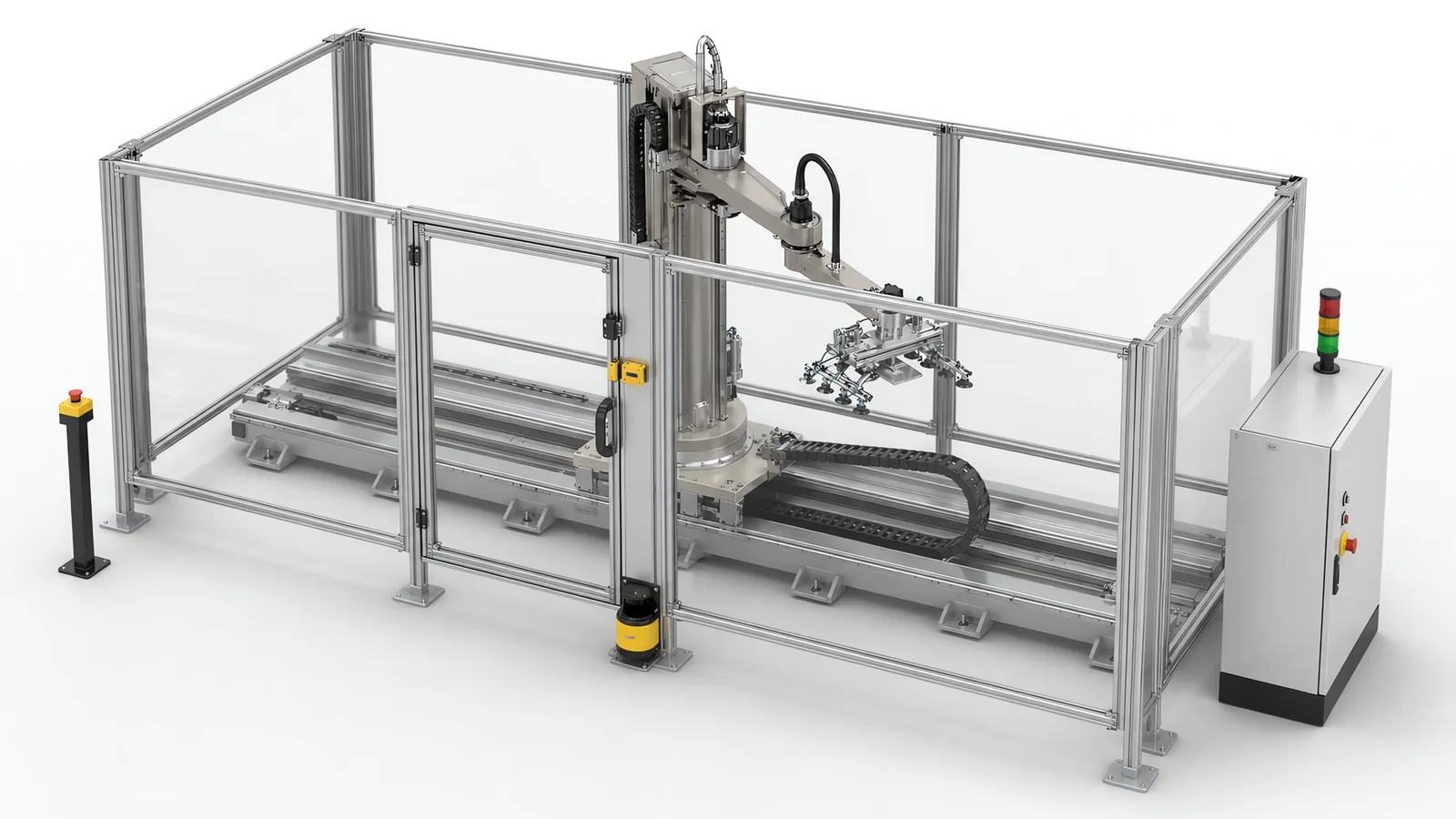
The ISO 10218 industrial robot safety standard has two parts: Part 1 covers the robot, and Part 2 covers its application and integration into a cell. The 2025 editions update the requirements that robot suppliers and integrators use to design and validate those systems.
For a buyer, the practical deliverables are the robot documentation, the application risk assessment and validation evidence from the built cell. Motionwell applies that division when integrating six-axis, collaborative and SCARA robots into custom machines in Singapore.
The short answer. ISO 10218 is two documents. ISO 10218-1:2025 covers the industrial robot as a product, meaning the arm, its controller and the safety functions built into it, and is answered by the robot manufacturer. ISO 10218-2:2025 covers the robot application and the robot cell, meaning the layout, the safeguarding, the end effector, the workpiece and the way the robot’s safety functions are used, and is answered by whoever integrates the cell. The 2025 revision adds robot classifications and safety-related cybersecurity requirements to Part 1. Part 2 incorporates most of the collaborative material from ISO/TS 15066 and addresses end-effector integration. ISO 13849-1:2023 supports the safety-related control design. For a buyer, the practical consequence is that the robot’s declaration and the cell’s assessment are two separate deliverables from two separate parties, and a quotation should name the edition, the part and the owner of each.
On the cells we build, the share we own is the Part 2 half of that split: the risk assessment, the safeguarding, the end effector, the safety circuit and the validation record behind them.
What Does the ISO 10218 Industrial Robot Safety Standard Actually Cover?
A robot cell is judged by a stack of standards, and ISO 10218 is the robot-specific layer in the middle of it. Above it sits ISO 12100, the general standard for machinery, which fixes the method: determine the limits of the machine, identify the hazards, estimate the risk, then reduce it in a fixed order of inherently safe design first, safeguarding second and information for use last. Beside it sits ISO 13849-1, which fixes how reliable a control-based safety function has to be once ISO 12100 has decided one is needed. ISO 10218 takes those two general documents and says what they mean when the machine contains a reprogrammable manipulator: which hazards a robot brings that a press or a conveyor does not, which safety functions a robot is expected to provide, and how a cell around it is to be safeguarded and verified.
That position explains what the standard does not do. It does not replace the risk assessment; it tells you what to look for while doing one. It does not rate a safety circuit; it points at ISO 13849-1 for that. And it does not cover the employer’s duties on the floor, meaning training, procedures and lockout, which sit with the plant regardless of what the builder did.
| Standard | Question it settles on a robot cell | Who applies it in a cell project | What you should end up holding |
|---|---|---|---|
| ISO 12100 | Which hazards exist, how big the risk is, and in what order it is reduced | The integrator, for the cell as a whole | A risk assessment covering every operating mode |
| ISO 10218-1:2025 | What the robot as a product must provide, by classification | The robot manufacturer | The declaration and the safety function specification for the arm and controller |
| ISO 10218-2:2025 | How the cell is laid out, safeguarded, integrated and verified, including collaborative operation | The integrator | The cell safety file and the validation record |
| ISO 13849-1:2023 | How reliable each safety function has to be and how that is demonstrated | The integrator for the cell circuits; the robot manufacturer for the functions inside the controller | Performance level calculations per safety function |
The right-hand column is the one to read at purchase. Every row produces a document, and each document has a different author. A cell where all four documents exist and name each other is a cell that can be reassessed later without starting from nothing.
What Do Part 1 and Part 2 Each Govern, and Who Answers for Each?
Part 1 is what the robot arrives with. The manufacturer designs the arm and controller to it, tests the safety functions the standard expects for the robot’s classification, and declares conformity. Nothing in that declaration knows what the robot will pick up, how fast it will move in your cell, where a person will stand, or what the gripper looks like. It could not know, because the robot was declared before the cell existed.
Part 2 is what the cell becomes. The integrator takes the robot, adds the end effector, the fixtures, the part presentation, the fencing or the sensing, the control panel and the interface to the rest of the line, and assesses the result as one machine. The safety functions the robot provides under Part 1 are inputs to that design; the cell’s safeguarding is built by using them, and it is verified on the built cell, never on the robot’s paperwork. Where a robot cell is delivered by us, this is the document set we produce, and the broader machine safety method behind it is on our machine safety and CE compliance page.
The confusion that costs money is treating the Part 1 declaration as if it covered the cell. It does not, and it never did under the 2011 edition either. A robot with a complete Part 1 file, placed in a cell with no Part 2 assessment, is an unassessed machine with a well-documented component inside it.
| ISO 10218-1 | ISO 10218-2 | |
|---|---|---|
| Object | The industrial robot: arm, controller, built-in safety functions | The robot application and cell: layout, safeguarding, end effector, workpiece, modes, interfaces |
| Who holds it | The robot manufacturer | The integrator, which for a custom cell is the machine builder |
| What it can tell you | What safety functions the robot provides and to what functional safety level, by classification | The measures and validation evidence for this cell, tool, workpiece and operating modes |
| What it cannot tell you | Anything about your tool, your part, your layout or your people | Anything the robot does not document under Part 1, which is why the two files have to name each other |
| When it is written | Before the robot is sold | After the cell is designed, and again after it is built and measured |
The final row matters for scheduling. Calculate safeguarding distances during design using the required inputs, then validate stopping performance and the installed distances on the completed cell. Include those checks on the factory acceptance test checklist and confirm site-dependent conditions after installation.
What Changed Between the 2011 Edition and ISO 10218:2025?
The changes affect both the robot and its application. Part 1 introduces robot classifications and safety-related cybersecurity requirements. Part 2 incorporates most of the collaborative material from ISO/TS 15066:2016 and addresses the integration of the tool and workpiece. The table separates these design and documentation questions.
| Change | Where it lands | What a cell buyer does with it |
|---|---|---|
| Robot classifications, each with matching functional safety requirements | Part 1 | Ask the robot supplier which classification the declaration names, and get the safety function specification that goes with it |
| Safety-related cybersecurity requirements | Part 1 | Ask who can change the safety configuration on the controller, how that is recorded, and where the controller’s network interface sits in the cell design |
| End-effector integration | Part 2, including clause 5.9 | Put the tool and workpiece into the application assessment, with a named design and assessment owner |
| Most of ISO/TS 15066:2016 on collaborative operation incorporated | Part 2 | Name ISO 10218-2:2025 as the primary reference for any collaborative application, and stop citing the technical specification alone |
| Reference to ISO 13849-1:2023 for control system safety functions | Part 1, applied through Part 2 | Review existing calculations, design assumptions and validation evidence against the selected edition |
Review the applicable changes against the actual cell. Compare the robot’s capabilities, end effector, access tasks, safety functions and validation records with the selected edition. The resulting gap list identifies which design measures remain suitable, which calculations or tests need updating and where hardware or software changes are required.
What Do the Robot Classifications Mean for the Robot You Are Buying?
The 2025 edition of Part 1 ties the functional safety requirements a robot has to meet to a classification of the robot. Under the 2011 text a buyer asked whether the robot conformed to ISO 10218-1, and the answer was yes or no. Under the 2025 text the useful question is which classification the declaration names, because the functional safety expected of the robot follows from that class for every arm on the market.
Use the robot manufacturer’s classification and safety-function specification as design inputs. For each function the cell relies on, confirm the supported mode, limits and declared functional safety level. These may include monitored speed, standstill, axis or workspace limits and stopping functions. Compare them with the cell requirements before selecting the safeguarding and interfaces.
For those three shapes the consequence is the same. A six-axis arm, a SCARA and a collaborative arm are all industrial robots under Part 1, each with its own declaration and its own classification. The collaborative arm is not exempt from Part 1 because it is marketed as collaborative; collaboration is an application property that Part 2 deals with, which is set out below. The choice between those shapes is a cycle time and reach decision first, covered in our comparison of what a cobot is and where it earns its place, and a safety file decision second.
Two things to ask the robot supplier at quotation stage, both cheap to ask and awkward to discover later. Which edition of Part 1 the declaration is written against, because arms already in stock may carry a declaration to the earlier edition. And whether the safety function specification, meaning the document that lists each function and its declared level, is supplied with the robot or has to be requested separately.
How Does Functional Safety Reach the Cell Through ISO 13849-1:2023?
ISO 10218-1:2025 references ISO 13849-1:2023 for safety-related control design. In the cell file, identify the design basis and declared performance of the robot functions alongside the basis used for the cell circuits. This makes the interfaces and any edition differences visible.
An older calculation remains evidence for the configuration and assumptions it assessed. When updating a cell, compare those assumptions and the affected functions with the selected requirements. Changes may involve the specification, software, architecture, hardware or validation, as well as calculations. The ISO 13849 machine safety page explains required Performance Levels and circuit design; the DGUV summary of the 2023 revision describes the edition changes.
A modification quotation should identify the affected functions, available evidence and work needed to close the gaps. How to scope that assessment is covered in our guide to machine safety risk assessment.
Why Does a Robot Safety Standard Now Include Cybersecurity?
Because the safety functions on a current robot are configured in software. The monitored speed limit, the workspace boundary, the standstill monitoring and the stop behaviour on a modern controller are parameters, set through an engineering interface and held in a configuration. A safety function whose parameters can be altered by anyone who reaches that interface has an integrity problem that no amount of hardwired guarding solves, and the 2025 edition of Part 1 recognises that by carrying safety-related cybersecurity requirements for the robot.
The practical reading for a cell buyer is narrow and specific. Securing the plant network is a different discipline with its own standard, and the zone and conduit design a machine sits inside is covered in our guide to IEC 62443 for machine builders. The robot safety standard approaches the same network port from the other side: it asks what happens to the safety functions if the controller is reached. Three questions follow from that, and they belong in the cell specification.
- Who can change the safety configuration. The safety parameters should sit behind a credential, and the record of who holds that credential belongs in the safety file, never in a commissioning engineer’s notebook.
- How a change is recorded. A safety configuration has a version, and the version validated at factory acceptance is the one recorded in the handover pack. A later change reopens validation of the functions it touches.
- Where the controller’s interfaces sit. The robot controller usually has a network interface for the cell PLC and an engineering interface for programming. The cell design decides which of those is reachable from outside the cell, and the safety file records that decision.
Include access to the validated safety configuration in the design and handover review. Record the permitted change process together with the software version and the validation evidence.
What Does the End-Effector Guidance Change for a Cell Buyer?
The tool and workpiece change the application hazards: a vacuum cup and a pointed gripper create different contact conditions, while payload changes stopping performance. End-effector integration belongs in the Part 2 application assessment. Universal Robots’ safety-function guidance points to ISO 10218-2:2025 clause 5.9 and ISO/TR 20218-1 for end-effector guidance.
On a custom cell the tool is designed by the integrator, bought from a gripper maker and adapted, or supplied by the customer. The guidance does not care which; it cares that the tool’s contribution to the hazard is assessed as part of the cell and that the assessment names its author. Two consequences follow for the buyer.
The first is contractual. If the end effector is customer-supplied, the quotation should say who assesses it, because the integrator cannot declare a cell safe around a tool it has not examined. If the integrator designs it, the tool assessment is part of the Part 2 file and should be visible in the quotation as a scope item.
The second is about change. Tooling changes more often than robots do. A new product variant, a different carton or a lighter fixture typically arrives as a tooling change, and each one is a reassessment trigger under the cell’s file even when the robot and the fencing are untouched. Designing the tool family at the start, so that variants stay within an assessed envelope of mass, reach and geometry, is cheaper than reassessing per variant. How that envelope is designed, and when a tool becomes a safety function in its own right, is set out on our robot gripper and end effector design page.
Where Did ISO/TS 15066 Go, and What Does That Mean for a Cobot Cell?
Much of the collaborative-operation material from ISO/TS 15066:2016 is incorporated into ISO 10218-2:2025. The technical specification remains published and is under revision in the ISO catalogue. Use the adopted Part 2 requirements for a 2025 application assessment and map any supporting TS material to the relevant requirement; incorporation does not mean every clause or annex is unchanged.
For a collaborative cell, Part 1 provides the robot-side requirements and Part 2 covers the application. The tool, workpiece and shared tasks determine which collaborative measures are needed. The evidence is discussed in our guide to ISO/TS 15066 and collaborative robots; the cobot safety standards guide introduces the application choices.
For a new specification using the 2025 editions, name Part 2 and the edition of each supporting reference. For an existing file, keep the original references traceable and record the changes found during reassessment.
What Does ISO 10218:2025 Mean When You Buy a Robot Cell?
It changes the list of things you should be handed, and it changes who you ask for each. The list below is what we would expect to see in a cell quotation this year, whichever integrator writes it.
| What you should receive | Ask whom | Standard and part | Why it matters at purchase |
|---|---|---|---|
| The robot’s declaration, naming the edition of Part 1 and the robot classification | Robot manufacturer, through the integrator | ISO 10218-1:2025 | Tells you which functional safety requirements the robot was built to |
| The robot’s safety function specification: each function and its declared level | Robot manufacturer | ISO 10218-1:2025 with ISO 13849-1:2023 | The cell circuit is designed around these; a missing function is found at validation otherwise |
| The cell risk assessment, covering every operating mode including setup, teaching, cleaning and recovery | Integrator | ISO 12100 applied under ISO 10218-2:2025 | The document the whole safety file hangs from |
| Performance level calculations for each cell safety function | Integrator | ISO 13849-1:2023 | Proves the guard door, scanner and stop circuits reach what the assessment demanded |
| The end effector assessment, with a named author | Integrator, or whoever supplies the tool | ISO 10218-2:2025 | The tool changes the hazard; unowned tools are unassessed tools |
| Justification of any collaborative operation mode, with measured contact or separation evidence | Integrator | ISO 10218-2:2025 | Proved on the built cell with the real tool and part, not on the arm’s datasheet |
| Safety configuration record: version, who may change it, where the controller’s interfaces are reachable from | Integrator, using the manufacturer’s controller functions | ISO 10218-1:2025 cybersecurity requirements, applied in the cell | The parameters that keep a person safe are software; their integrity has to be evidenced |
| Validation record from factory acceptance: stopping performance measured, each safety function exercised | Integrator | ISO 10218-2:2025 | The Part 2 file is not complete until the cell has been measured |
Three points sit around that table.
Review changes to an existing cell. New tooling, workpieces, modes, location or controls can affect the original assessment. Define the reassessment basis and review the affected hazards and functions. Price any design changes, calculations and validation as part of the modification scope.
The robot shape does not decide the safeguarding. A six-axis arm, a SCARA and a collaborative arm can each end up behind fencing or in a shared workspace, depending on what the application assessment finds. A collaborative arm with a sharp tool in a fast cycle ends up fenced; a six-axis arm in an enclosed process may be safeguarded by the enclosure it already sits in. The assessment answers this, and the guarding design that follows from it is on our machine guarding design page.
The standard tells you what to ask. The items in the table are each work. Which of them moves the price of a cell, and by how much relative to the arm itself, depends on the application, and that is the subject of our guide to what drives the cost of an industrial robot cell. What the standard does is make each item visible early enough to be priced, instead of arriving as a surprise at commissioning.
When Is ISO 10218 Not the Question You Should Be Asking?
Five situations put the real question somewhere else, and naming them early saves a safety file that answers the wrong one.
The hazard is the process. Where the workpiece is hot, energised, sharp or under pressure, the robot is the least of the cell’s hazards, and a file that spends its pages on robot classifications while the workpiece goes unassessed has missed the point. ISO 12100 governs that assessment, and the robot layer sits inside it.
There is no reprogrammable manipulator in the machine. A fixed-stroke pneumatic transfer, an indexing table or a conveyor is machinery, assessed under ISO 12100 and ISO 13849-1 without the robot-specific layer. Citing ISO 10218 on a machine without a robot in it adds nothing except a document the assessor has to explain.
The robot is inside a standard machine you bought complete. A packaged machine that happens to contain a robot arrives with its own manufacturer’s declaration for the whole machine, and the Part 2 work was done by that manufacturer. Your question is then the interface between that machine and your line, which is a different scope, covered on our robot integration services page under the heading of what an integrator owns.
The gap is on the floor. A cell with a complete file and a habit of running with the door interlock bridged is not made safer by a better file. Training, procedures and lockout are the plant’s duties, and no edition of any standard transfers them to the builder.
Nobody will own the file afterwards. A custom cell assumes a maintenance organisation that will reopen the safety file when the tool changes. Where that organisation does not exist yet, building it belongs in the project: name the person who owns the file, put the reassessment triggers in the handover pack, and budget the first tooling change as a reassessment.
What Does the 2025 Split Mean for Your Safety File?
Use the Part 1 and Part 2 split to assign the evidence. Obtain robot capability and safety-function information from the manufacturer, then agree the application assessment and validation plan with the integrator. Include that evidence in the delivery schedule alongside mechanical design, controls work and acceptance testing.