
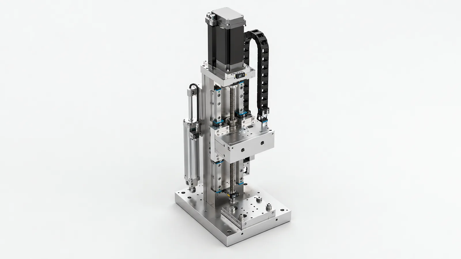
Motionwell Automation designs servo lift systems and precision positioning axes in Singapore as part of the special purpose machines we build, and on a vertical axis a control fault becomes a falling load unless something mechanical is holding it. The delivered vertical axes run from a truss manipulator with four picking units on a long travelling beam, through the Z columns on our linear gantry series, where the compact aluminium-extrusion frame carries light payloads on a short Z stroke and the double-beam builds carry heavy ones on a long one, to the column palletizing robot whose J2 axis is a purely vertical lift on a counterbalanced column. At the fine end the same discipline shows up as a servo-driven screw axis pushing a load cell at 0.05 mm per second on a button actuation force tester, and as motorised XYZ linear modules with micrometre resolution on a panel alignment station.
Machines are designed, assembled and tested at our Woodlands Link facility, and the company has delivered more than 150 special purpose machines since 2014 under ISO 9001:2015 and bizSAFE Level 3.
The short version comes first. Gravity does not switch off when the drive does, so on a vertical axis three things stop being accessories and become design items: what holds the load at standstill, what holds it when power is removed, and what happens on the way down if neither works. Holding torque, the brake, the counterbalance and the power-loss test all exist to answer one question, which is where the load is one second after something failed.
The axis is designed around catalogue components on whichever control platform your plant already runs, with catalogue pneumatics and cable carrier, because an axis whose consumables sit on a distributor shelf comes back up in a shift while one built from our own drawings comes back up on our lead time. The motor-selection argument in general form is in our note on servo and stepper motor drives, the gantry and Z-column work it feeds is on the machine tending automation page, and the safety architecture behind a brake used as a safety function is on the machine safety and CE marking page.
Why Is a Vertical Axis a Different Problem From a Horizontal One?
On a horizontal axis the load is a mass; on a vertical axis it is a mass plus a constant force that never lets go. A horizontal axis at rest needs no torque. A vertical axis at rest needs the torque it needed while lifting, indefinitely, and the failure of that torque has a direction. That difference propagates through the whole design.
| Design item | Horizontal axis | Vertical axis |
|---|---|---|
| Torque at standstill | Near zero once the move ends | Full gravity load, for as long as the axis is stopped |
| Motor sizing | Acceleration and friction | Acceleration plus a gravity term present on every move, both directions |
| Duty and heating | RMS torque across the move profile | The same, plus every holding period, unless a brake takes the holding duty |
| Loss of drive power | The axis coasts and stops | The axis descends unless something mechanical holds it |
| Backlash and lost motion | A position error either side of the target | Takes up one way only, so approach direction changes the answer |
| Overload | The axis stalls in place | The load can drive the motor backwards |
| Commissioning risk | A crash costs a part and a fixture | A crash can cost the moving assembly and whatever was under it |
The other consequence is regulatory, and it arrives late in a project when it is expensive. Singapore does not require CE marking, but the Workplace Safety and Health Act requires dangerous parts of machinery to be securely fenced, and machines incorporating lifting equipment must be examined and certified by an approved authorised examiner before use, with periodic re-examination after. Whether your lift axis counts as lifting equipment is settled at concept stage.
Ballscrew, Belt or Rack: Which Drive Belongs on a Lift Axis?
The horizontal and vertical answers differ, because the question changes from which drive is stiff and long enough to which one is holding the load, and what it does when it breaks.
| Drive on a lift axis | Behaviour under gravity | Suits | Where it fails |
|---|---|---|---|
| Ballscrew | Efficient, so it back-drives readily; the lead gives the reduction that shrinks reflected inertia and motor size | Precise vertical positioning, moderate strokes, high stiffness, press duty | Long strokes, where critical speed limits rotation rate; needs a brake and debris protection |
| Lead screw, low lead | Can be self-locking through friction, a property of thread and lubricant | Slow, low-duty adjust axes where holding without power is worth the lost efficiency | Efficiency, heat and wear at duty; self-locking degrades as the nut wears |
| Timing belt | A spring in the loop that stretches under load, and total loss of holding if it breaks | Long, fast, light vertical strokes at modest payload | Stiffness and settling, and any case where belt failure is unacceptable without a catch |
| Rack and pinion | Positive engagement, splices to arbitrary length, back-drives freely | Long travel, heavy payloads, gantry columns and travelling axes | Backlash unless preloaded or twin-pinion, and debris in an open-toothed run |
| Chain or cable hoist | Holds by wrap and by the hoist’s own brake | Heavy lifts where positioning tolerance is coarse | Precision, since accuracy is limited by the compliance of the flexible element |
Our delivered mix follows that split. On the linear gantry series the X axis runs rack and pinion because rack splices to arbitrary length, the Y axis uses a ballscrew or a timing belt depending on the class, and the Z columns run on high-precision linear guides. The compact aluminium-frame gantry in the lightest payload class is belt-driven throughout, which is a legitimate answer there and a poor one at ten times the load. On the low-profile robot linear track the drive is a servo motor with a planetary gearbox onto ground-grade rack and pinion, giving plus or minus 0.5 mm repeat positioning inside a 100 mm overall track height. On the column palletizer the vertical column uses a ballscrew or rack-and-pinion drive with a counterbalance mechanism.
Guide choice is part of the drive decision: a lift axis carries an overhung tool, so the moment on the carriage usually sizes the rail. And in a dirty environment an open screw or rack is a maintenance item, which is why our dual-rail truss manipulators for dusty and harsh environments use V-groove roller guides, which shed debris that a recirculating ball guide would carry back into the raceway.
What Is a Motor Brake Actually Rated to Do?
It is rated for less than most specifications assume, and the rating is rarely checked. A servo motor brake is generally spring-applied and electrically released: remove the current and the spring clamps the rotor. That is the right behaviour for a power failure, and also where the confusion starts, because holding a stationary load and stopping a moving one are different jobs with different ratings.
Read three figures off the motor datasheet before treating a brake as a safety measure. Static holding torque, which has to exceed the gravity load with margin at the worst case, including the heaviest tool you will ever fit. Permitted braking energy per stop and permitted number of emergency stops, because a holding brake asked to decelerate a moving load repeatedly is a consumable worn out on a duty it was not bought for. And engagement delay, because between the drive dropping torque and the brake gripping there is a window in which nothing holds the load, and that window has a distance attached to it.
| What holds the load | What it is actually rated for | How it fails | How you verify it |
|---|---|---|---|
| Spring-applied motor holding brake | Holding a stationary rotor at rated static torque | Wear from repeated dynamic stops, contamination, corrosion, a release circuit stuck energised | Power-removal tests at worst-case load, repeated periodically |
| Self-locking screw geometry | Nothing in the safety sense; friction | Wear, lubricant change, vibration | Not the only protection where a person can be underneath |
| Counterweight | Balancing a known, constant mass | The payload changes and the balance no longer matches; the weight is a second falling hazard | Static balance check across the payload range |
| Gas spring or pneumatic counterbalance | Reducing average torque demand | Gas springs lose force over life and vary with temperature; a pneumatic counterbalance falls with the air unless a pilot check valve holds it | Measure assist force at both ends of stroke, and test air loss |
| Mechanical prop, pin or scotch | Holding the axis during maintenance | Being optional, so it is not fitted at the moment it is needed | Procedure and physical interlock |
Counterbalance deserves a decision. Balancing the axis lowers the torque the motor makes in both directions, which is how the column palletizer gets away with a smaller servo, and it lowers the energy a stop has to absorb. What it does not do is hold position, and each method brings a failure of its own: a counterweight is a second mass that can fall, a gas spring loses force over its life, and a pneumatic counterbalance is only as reliable as the air.
One line decides the specification: a brake fitted because the servo would otherwise cook itself holding current is a machine component, and a brake fitted because a person can stand under the load is a safety function. Where it is the second, it has to be architected, rated and validated like any other safety function, with the required performance level derived from the risk assessment under ISO 13849-1:2023, and the usual questions follow about channels, monitoring, diagnostic coverage and how the machine proves the brake still works. Which of the two you bought is a risk assessment output, and the method is on our machine safety and compliance page.
What Does the Machine Do When the Power Goes Away?
Design this case explicitly, and write the test into the acceptance plan, because a power-loss test only gets run if the plan calls for it.
Safe Torque Off prevents the drive from generating torque. A vertical-axis design also needs a defined way to control deceleration and hold the load. The safety sequence coordinates the drive, brake and any mechanical or pneumatic load-retention devices, with engagement delays and stored energy included in the assessment.
Test the sequence with the representative tool and load, including a supply failure during motion. Record stopping distance, brake engagement and load movement after the drive is disabled. Those results verify the holding arrangement and the recovery procedure for the completed lift.
Two related decisions belong in the same conversation.
Absolute encoders on vertical axes. On long gantry and track axes we specify servos with absolute encoders, which removes the homing routine, holds position knowledge after power loss and supports dual-motor gantry synchronisation. On a vertical axis that stops being a convenience, because homing an incremental vertical axis means moving a suspended load in an unknown state, sometimes with the guard open because somebody is working out why it stopped.
Where the load ends up. If a slow descent is acceptable and a fast one is not, a controlled lowering path may beat a brake alone. If no descent is acceptable, the answer is physical: the load is never over the place a person stands, or there is a mechanical catch.
Servo or Stepper When a Dropped Load Is the Failure Mode?
Select the motor, feedback and load-retention arrangement together. Position feedback detects a departure from the commanded move; the brake or other holding device manages the load when drive torque is removed.
An open-loop stepper receives commanded pulses without measuring whether the rotor followed them. A closed-loop stepper adds feedback and fault detection. For either type, size the axis against the manufacturer’s torque-speed curve, load inertia, duty and supply conditions, then define how the load is held during a stop or power loss.
A servo provides position feedback and following-error monitoring with programmable motion control. Its continuous and peak torque ratings must cover the lifting cycle, and the brake sequence must suit its holding or stopping duty. Commissioning tests verify the complete arrangement under the representative load, including interrupted motion and recovery.
| Option on a loaded vertical axis | Where it fits | What you give up |
|---|---|---|
| Servo with brake and absolute encoder | Any lift where position matters, the load is heavy, or a descent is unacceptable | Cost, gain tuning at commissioning, and a parameter backup somebody owns |
| Closed-loop stepper with brake | Light adjust axes where an alarm on stall is enough and duty is low | It alarms on a stall but does not change the torque-speed curve, so it will not rescue an undersized axis |
| Open-loop stepper | Light, slow auxiliary axes where a lost step is recoverable at the next home cycle, a narrow set on a vertical axis | Any ability to detect its own failure, the property the vertical case needs most |
| Pneumatic cylinder | Two-position lifts, clamps, gates and ejectors, where force in a small package beats a profile | Intermediate positions, controlled velocity, force accuracy, position confirmation between the ends |
| Hoist or jack with an integral brake | Heavy, slow lifts with coarse positioning tolerance | Positioning resolution and cycle rate |
There is a second reason the closed-loop axis pays on a lift, unrelated to dropping anything. The torque signal is a free process signature. On a multi-station rotary assembly machine we would put a load cell on every press station and record the force-displacement curve against the part identity. On a lift axis the same signal is condition data: the torque needed to hold a known load measures what the mechanism is doing, and a trend that climbs over months is a guide, a screw or a brake telling you something before it tells you loudly.
Resolution, Repeatability and Accuracy: Which Number Are You Buying?
Specifications go wrong here often, because the three words get used interchangeably and are bought in completely different places.
| Term | What it means | Where it actually comes from | What it does not tell you |
|---|---|---|---|
| Resolution | The smallest increment you can command | Encoder counts and transmission ratio; the easiest of the three to raise on paper and the least useful on its own | Whether the axis can move that far, or whether it stays there |
| Repeatability | The spread when the axis returns to the same target | Preload, guide quality, homing method, thermal state, and approach direction | Whether the target was the right place |
| Accuracy | How close the axis gets to the true target | Screw or rack lead error, coupling wind-up, backlash, thermal growth, and the calibration behind the datum | Anything about the part, which is what your quality engineer measures |
A 23-bit servo encoder resolves the shaft to a level no mechanical transmission can honour, so pick the motor for torque, dynamics and feedback, then buy accuracy from the transmission, the homing strategy and inline measurement. Where dimensional truth matters we verify with an external measurement. On a copper-plate thickness measurement machine, a laser displacement sensor did the judging while the axis did the positioning. The encoder reports where the motor went, and says nothing about backlash, screw wind-up, thermal growth or the thickness variation in the plate itself. On a multi-station rotary indexing machine the dial repeatability is a figure we would measure at the tooling plate under load, never from the indexer datasheet, as set out in our guide to how we design multi-station rotary assembly machines.
Two additions specific to a vertical axis. State the approach direction with the repeatability figure, because backlash and droop take up one way only. And state the load, because deflection under a light tool and under a heavy one are different numbers on the same machine.
Then check the figure against what the product holds. On the column palletizer, the repeat accuracy worth paying for was set by the corrugated case, because the cases hold plus or minus 2 to 3 mm on their own dimensions. On the panel alignment station at the other end of the range, motorised XYZ linear modules with micrometre resolution earn their cost by compensating for panel warpage and edge trim tolerance that would otherwise propagate downstream. Same discipline, opposite conclusion, decided by the part.
What Sets Settling Time, and Why Is Stiffness Usually the Answer?
A servo axis cannot be tuned stiffer than the structure it is bolted to, which is why stiffness is usually the answer. The motor, screw, coupling, carriage, tool plate and frame form a spring-mass system, and the first structural resonance of that assembly is the ceiling on useful loop gain. Push the gains past it and the axis oscillates around the target, which reads on a scope as a controller problem and is really a mechanical one.
Two consequences follow for how a lift axis gets quoted. A tall column is a cantilever with the tool at the far end, and stiffness falls quickly with unsupported length, so a Z stroke specified generously because it might be useful later is not free. Overhang does the same thing sideways: the further the tool sits from the guide rails, the lower the first resonance and the longer the settle.
Cycle time is where this becomes money. A datasheet move time is measured gate to gate with a dummy load and nothing else happening, while the real cycle adds vision acquisition and processing, settling before the vacuum releases, gripper actuation and the PLC handshake. Those additions usually decide whether a station makes rate, which is why we time them on the actual parts before quoting a throughput figure. On a lift axis settling is often the largest of them, because the axis that has to be still is carrying the mass that makes it ring.
When Does a Servo Axis Earn Its Place Over a Pneumatic Cylinder?
Pneumatic cylinders suit compact, repeatable end-to-end movements such as clamping and transfer on our tray-fed filling platform. Guided mechanisms carry side loads, and position sensors confirm the movement before the PLC advances. Material, seals and lubrication are selected for the cleaning procedure and environment. A servo axis becomes useful when the task calls for programmed intermediate positions, velocity profiles or recorded force and position data.
Air stops paying at four points: when you need intermediate positions, controlled velocity, force accuracy or force data, or position confirmation between the ends. The vertical case adds two more. A cylinder holding a load is holding it with air, so losing supply pressure moves the load unless a pilot-operated check valve or a mechanical lock holds it, and the power-loss question simply comes back in a different utility. And speed control on air is open loop: flow restrictors drift with temperature, supply pressure, seal wear and lubrication, so the profile commissioned in January is not the one running in June, and on a vertical axis that drift has a direction because the down stroke is assisted by the load and the up stroke is opposed by it.
One class of machine buys the electric axis for none of those reasons. On control system modernisation work, now the largest single stream we run, a cam-driven axis is not adjustable, so a new product variant becomes a machining job; a servo with an electronic cam profile turns it into a recipe change.
What Belongs in the Acceptance Plan for a Lift Axis?
All of it is testable, and the items people leave out are the ones that matter after handover. Ask for them in writing before the machine is built, because a test written into the plan is cheap and a test invented at the acceptance run is an argument.
A power-loss drop test at worst-case load. Remove drive power deliberately, at the top of the stroke, with the heaviest tool and the heaviest part fitted, and measure how far the load travels before it is stationary. Repeat it warm, because a hot brake and a cold brake are not the same brake. Run the emergency stop path separately from the supply-failure path: different sequences, different timings, and both have a distance.
Holding at load, over time. Park the axis at height, loaded, and leave it. Drift is a leaking counterbalance, a slipping brake, or a drive quietly holding what the brake was supposed to hold.
Repeatability with the direction and the load stated. Rising and falling approaches, at the payloads you run, at the position where the tool works, never at a convenient mid-stroke point.
Settling measured on the built axis. Time from move complete to a position stable enough for the next operation, at full extension, with the tool fitted. That number belongs in the cycle time calculation.
A soak test long enough to produce a wear interval. The consumables are the brake, the screw or rack, the guides, the lubricant and the cable carrier, and a soak test turns each into an interval the maintenance schedule can carry.
Factory acceptance testing happens at our Singapore facility before shipment, which is the practical argument for a local buyer working with a local builder here: a lift axis gets adjusted after it is built, and those adjustments happen in hours when the builder is in the same industrial estate. Where the machine is regulated, that evidence feeds the qualification package, as set out on our computer system validation page.
When Should You Not Buy a Custom Servo Lift?
Three situations rule it out, and each one is cheaper to find before a frame is drawn.
The move has two ends and nothing in between. A clamp, a gate, a stop or a two-position lift is a cylinder with reed switches, and dressing it up as a servo axis buys tuning, cabling and a parameter backup for nothing.
A standard product covers it. Electric rod actuators, catalogue linear stages, screw jacks and packaged lift columns are proven products with stocked spares, and where one covers your stroke, load and duty it will usually cost less than an axis designed from scratch. That is the recommendation you get at concept review, and establishing it costs a conversation.
A person can stand under the load and nothing but the control system prevents it. That is a guarding and mechanical-restraint problem, and a better servo does not touch it. Hoists, cranes and lift tables are a different equipment class again, with their own certification path.
What we do build is the axis inside a machine: the frame and column, the drive and guide selection, the brake and counterbalance decision, the safety architecture around both, the control system, and the acceptance evidence. We support your conformity work on it, including LVD and CE testing and Ministry of Manpower lifting certification where the machine includes lifting equipment. The gripper hanging off the axis is on our end of arm tooling page, and where the lift is one axis of a larger cell the integration scope is on our robot integration services page.
Standards Used in Machine Design and Validation
These references inform the design, testing and documentation described on this page. Each row links to its primary source and records the edition checked.
| Standard | Current edition | What it means for your machine |
|---|---|---|
| ISO 13849-1: Safety of machinery, safety-related parts of control systems | ISO 13849-1:2023 | Provides the design method for safety-related control functions, including architecture, component reliability, diagnostic coverage and common-cause failure measures. The machine risk assessment establishes the required Performance Level; design calculations and validation provide the evidence for each function.Checked 1 Sep 2026 against ISO 10218-1:2025 normative references |
Frequently Asked Questions
Does a servo lift axis need a motor brake?
Assume yes, and make the exception argue its case. A servo draws current in proportion to load, so on a vertical axis holding against gravity it draws real current all the time it is stopped, which is why we specify a motor brake on vertical axes, so nobody pays for continuous holding current. The brake also covers the case the holding current cannot: when drive power is removed, whether by an emergency stop, a trip or a supply failure, the motor makes no torque at all. A horizontal axis coasts to a stop. A vertical axis descends. The brake is what turns the second case back into the first.
Ballscrew or belt on a vertical axis?
Ballscrew for load and stiffness, belt for stroke and speed, and the failure mode decides the argument more often than the duty does. A ballscrew is stiff, positions well and gives mechanical reduction, so the motor sees a smaller reflected load; it is also efficient enough to be back-driven by gravity, which is precisely why the brake is not optional. A timing belt is light, cheap over long travel and forgiving of debris, but it is a spring in the loop, so it stretches under load and it drops the load outright if it breaks. Our compact aluminium-frame gantry is belt-driven in its lightest payload class, which is a legitimate answer there and a poor one at ten times the load.
Can I use a stepper on a loaded vertical axis?
Only where a dropped load costs nothing, which on a vertical axis is rare. A stepper runs open loop: the drive counts pulses out and does not know whether the rotor arrived, so a lost step is silent and the axis reports a position it is not at. On a horizontal axis that is a misplaced part and a re-home. On a loaded vertical axis the same event is the load descending under gravity with the HMI showing green. A stepper also loses torque as speed rises, and gravity does not, so the worst torque demand and the weakest part of the curve can meet on the same move. Closed-loop steppers alarm on a genuine stall but do not change that torque-speed curve.