
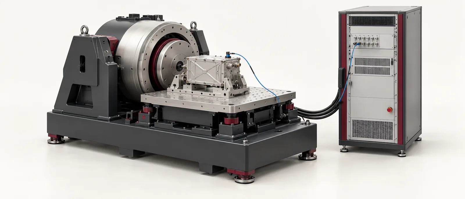
Conceptual equipment illustration.
A vibration testing machine should be sized against the required vibration profile and the complete moving assembly: specimen, fixture and the relevant moving parts of the shaker. The selection also depends on frequency range, displacement, velocity and the way vibration is measured and controlled at the test article.
This is a product test system. It is different from a sensor network that observes vibration on operating factory equipment. The automated test equipment scope should state whether the project needs controlled excitation, measurement, automated sample handling, or all three.
Specify the Test Profile First
Write down the required test mode and the source of the test profile. A sine sweep, random vibration and a shock test describe different inputs. Their ratings cannot be compared using one isolated acceleration number.
HBK’s vibration applications overview treats the shaker, sensors, acquisition and analysis as parts of a measurement chain. Its vibration test equipment range also separates exciters, power amplifiers and control software. Ask for a proposed configuration against your complete test envelope.
| Input | Why the equipment supplier needs it |
|---|---|
| Test profile and duration | Establishes the required excitation and operating duty |
| Frequency range | Determines whether the equipment covers the full profile |
| Specimen and fixture mass | Contributes to the moving load and required force |
| Dimensions and centre of gravity | Affects mounting, overturning loads and fixture design |
| Axis or axes | Defines how the specimen is oriented and supported |
| Control and response channels | Defines where input is controlled and where behaviour is observed |
| Environmental requirements | Identifies chamber, temperature or other interface needs |
For preliminary reasoning, force, mass and acceleration are related by F = m × a. This relation is useful for understanding why a heavy fixture matters. A shaker selection still has to account for its operating envelope and the dynamics of the assembly, so do not reduce a broadband test to a single static calculation.
The Fixture Becomes Part of the Dynamic System
A fixture that is rigid under a slow load can behave differently when excited over a frequency range. Its resonances and mounting arrangement can alter the motion delivered to the specimen. Include it in the mechanical design and simulation review, along with the attachment interfaces and bolt access.
Keep the load path short and support the specimen in the intended orientation. Record fixture mass and the fastening arrangement as controlled test configuration items. Changing either may change the test response even when the controller runs the same programme.
An adapter plate added during commissioning is therefore an engineering change, not just a convenient way to make the bolt patterns fit. Recheck the configuration after it is introduced.
Distinguish Control Sensors From Response Sensors
The controller needs a defined measurement of the applied input. Additional sensors may observe the specimen’s response at other locations. Record those roles explicitly, because moving a control sensor changes what the system is trying to reproduce.
Document sensor identity, mounting method, direction and cable route. A loose mount or a cable rubbing against the specimen can produce a misleading trace. Include a photograph or drawing of the agreed sensor arrangement in the test setup record.
For a laboratory containing multiple instruments, laboratory automation can coordinate identities and records while the vibration controller remains responsible for the excitation task. Avoid making a general scheduling application responsible for the real-time control loop.
Diagnose an Unexpected Peak Before Changing the Profile
When a response differs from expectation, compare the actual assembly against the approved setup. Check mounting tightness, sensor placement, fixture revision and specimen orientation. Then compare control and response traces to identify whether the difference is in the delivered input or in the specimen’s behaviour.
Retain the original run and document the changed setup. Quietly editing the profile until a trace looks acceptable removes the basis for comparing the test with its requirement.
Accept a Repeatable Setup
Add the test profile, fixture drawing, sensor layout and configuration files to the factory acceptance test plan. Demonstrate loading, the agreed test sequence, controlled termination and saving the complete result under the correct sample identity.
Building a vibration test station into a laboratory or production process? Discuss the setup with Motionwell. We can help define the handling, fixture and instrument interfaces around the test.