
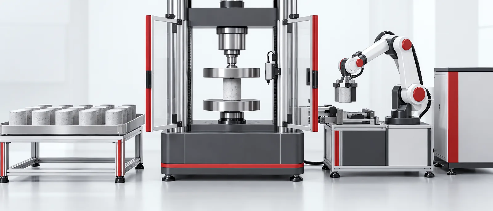
Conceptual equipment illustration.
Choose a compression testing machine from the result you need, then specify the specimen, force range, contact surfaces and displacement measurement. For materials and manufactured parts, a universal testing frame with appropriate compression tooling can cover several methods. An automated loader adds another requirement: it must reproduce the specimen position and handling conditions of the agreed test.
This guide focuses on material specimens and production components, including their integration into a laboratory automation system. Concrete cube crushing has different specimen, capacity and method requirements, so a machine selected for that task is not an interchangeable purchase.
Define What the Test Must Report
Peak force, force at a specified deformation and compressive modulus answer different questions. A package component may need a load-versus-displacement curve; a material study may need stress and strain calculated from controlled specimen dimensions. Put the required result and its calculation in the purchase specification.
ZwickRoell’s compression testing overview describes test frames fitted with application-specific platens or tooling. Its selection criteria include specimen geometry, material, temperature and expected force. Use those inputs to define the working configuration, not just a catalogue capacity.
For each specimen family, record:
| Input | Decision it supports |
|---|---|
| Geometry and contact faces | Platen size, seating and fixture access |
| Expected minimum and maximum force | Frame capacity and usable load-cell range |
| Required travel and installed tooling height | Available test space throughout the stroke |
| Result and test method | Control sequence and measurement channels |
| Conditioning and waiting time | Storage and handling around the instrument |
If the laboratory also needs tensile testing, compare shared-frame configurations against the separate gripping and strain requirements in the tensile testing machine guide.
Check the Contact Before Comparing the Curve
The specimen should meet the tooling as the method intends. Uneven end faces, an off-centre load or a fixture touching an unintended surface can change what the test measures. Ask the supplier to show the actual specimen seated in the proposed tooling, with enough access to inspect and clean the contact faces.
Instron’s ASTM D695 application guide explains platen parallelism and application-specific support for thin specimens. It is a rigid-plastics example, not a universal recipe for springs, foam or assembled products. The selected method determines whether a spherical seat, a rigid arrangement or additional specimen support belongs in the setup.
Specify how tooling is located after removal. A fixture that fits the mounting holes can still leave its contact surface in a different position after changeover. Include reseating checks in the acceptance trial.
Decide Where Displacement Is Measured
Crosshead movement and specimen deformation are different quantities. The frame, tooling and contacts can contribute to the measured travel. For stiffness or modulus work, identify the measurement location and the verified range of both the force and deformation channels. Instron’s D695 guidance discusses direct strain measurement and compliance correction under different measurement requirements.
For a component test, write down whether displacement means platen separation, local deformation or actuator travel. Save that definition with the result. Otherwise, two quotations can promise the same resolution while measuring at different points.
The analogous issue in a vibration testing machine is the distinction between the controlled input and the specimen response. In both cases, the sensor position belongs in the specification.
Automate Loading Without Losing the Test Conditions
A loading robot needs somewhere repeatable to grip and somewhere unambiguous to release. Design the nest and approach path together with the compression tooling. Confirm seating before starting the method, then define removal for both intact specimens and fragments.
Keep sample identity attached to the test request. A practical interface sequence is: identify the specimen, confirm loading, select the method, acknowledge readiness, start the test and collect the completed result. A timeout should leave a visible unresolved job, not an invented pass result.
Motionwell’s QA laboratory automation case study documents instrument tending and result handling for tensile and puncture tests. Its command and result interfaces provide a useful starting point when planning the handling around another test method, including compression.
Compare the Complete Acceptance Scope
Ask each quotation to identify the tooling, measurement channels, method setup and data export included. Then agree a trial using representative specimens across the intended working range. For destructive tests, compare matched specimens under controlled preparation and conditioning; a crushed specimen cannot provide a second independent run.
Check whether the final record preserves the sample identifier, method version, force and displacement units, result calculation and any interrupted test. Test a changeover and a failed loading attempt as well as a normal cycle.
Planning an automated compression test station? Discuss the specimen handling and instrument interfaces with Motionwell.