
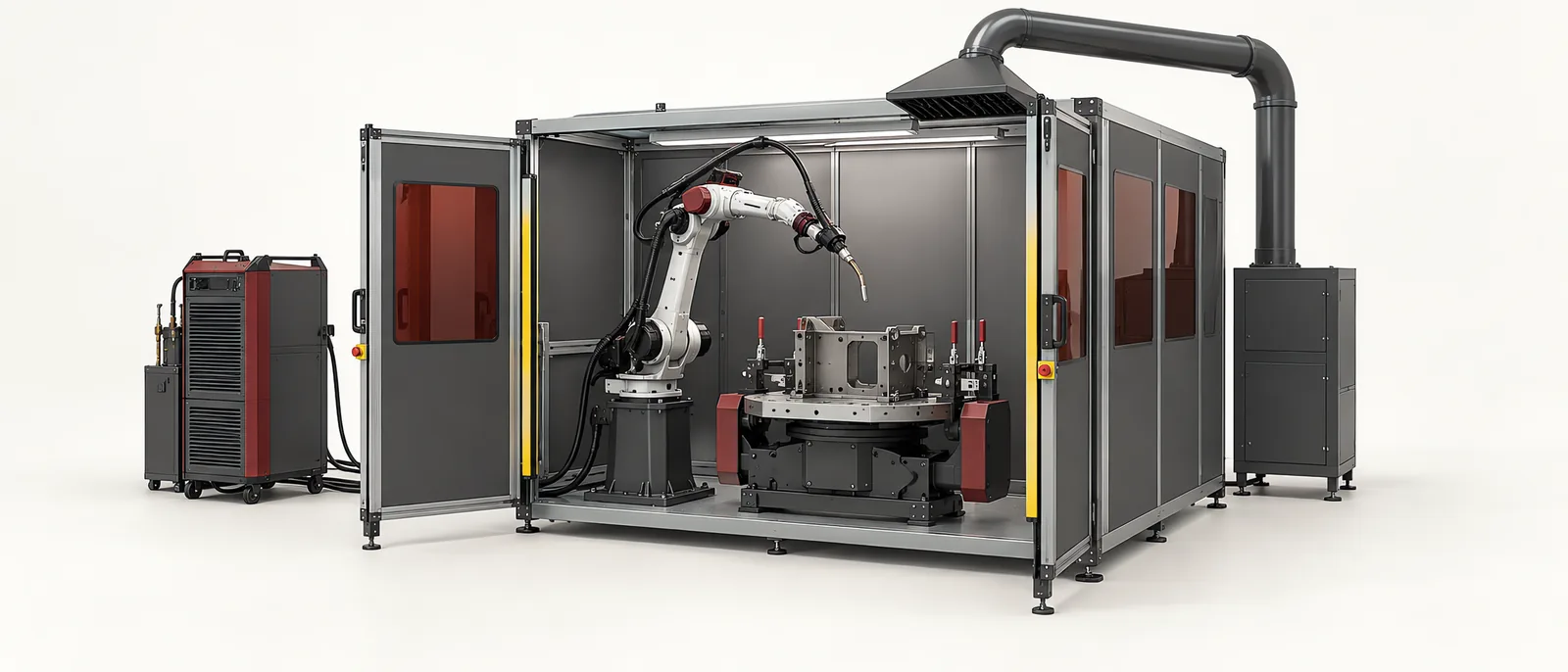
Conceptual equipment illustration.
Robotic welding combines controlled robot motion with a welding process, a repeatable joint and a fixture that keeps the workpiece accessible. A robot can repeat a programmed path, but the resulting weld still depends on fit-up, consumables, process settings and the condition of the equipment.
This guide focuses on an arc-welding cell. Spot welding and laser welding use different process equipment and joint requirements; they should be scoped as separate applications within robot integration.
Begin With the Joint and the Loading Method
Identify each joint, its required access and how the assembly is located before clamping. Separate variation in the incoming parts from movement caused by the fixture. A programme that succeeds on one carefully aligned sample may need a different locating arrangement for normal production parts.
Review the welding sequence with the process specialist. Clamps that provide good support at loading can obstruct the torch later. Thermal distortion can also change the position of subsequent joints. Include loading, welding and unloading states in the mechanical design and simulation review.
A positioner can present different faces to the torch. The ABB workpiece-positioner range includes equipment for coordinated motion with the robot. For a proposed cell, check fixture-plus-part load, orientation, cable routing and access throughout that motion.
Divide the Cell Into Clear Responsibilities
| Element | Responsibility to define |
|---|---|
| Fixture | Locate the assembly and confirm the required clamp state |
| Robot and positioner | Reach the joints with the intended torch orientation |
| Welding power source | Execute the selected process programme and report its state |
| Cell controller | Coordinate loading, permissions, faults and recovery |
| Torch service equipment | Maintain the tool condition and check the tool centre point |
| Quality checks | Establish whether the completed joint meets its acceptance criteria |
The fixture-ready signal should represent a known condition, not merely completion of a timer. Keep the welding-complete signal separate from the required weld-quality acceptance results.
Plan Torch Maintenance Into the Cycle
Spatter and tool damage affect a welding cell in ways that path programming cannot correct. Reserve space and access for cleaning, wire preparation and tool checks. Establish how often the cell performs these actions and what conditions trigger an additional check.
ABB’s Torch Service Center guidance identifies cleaning, wire cutting and tool-centre-point verification as process-support tasks. It also highlights tool changes and collisions as reasons to recheck the torch position.
A useful recovery trial deliberately stops the sequence between operations. Confirm whether the controller resumes, repeats a weld or routes the part for review. Automatic continuation is not suitable for every interrupted joint.
Cost the Production Cell, Not Only the Arm
The equipment list should include fixtures, positioners, process services, extraction, guarding, programming and verification. Product-family changes can require additional tooling even when the same robot remains in place. Our industrial robot cost-driver guide separates these integration costs from the arm itself.
Protective measures belong in the machine design. Arc radiation, hot material and process emissions remain relevant even when the robot is a collaborative model. The robot-cell safety standard guide explains the wider integration context.
Use Two Acceptance Records
Keep a cell-function record for loading, clamping, motion, faults, traceability and restart. Keep a weld-quality record for the agreed inspection or test results on representative joints. Link both records to the part and programme revision.
This makes a failure actionable: the team can distinguish an equipment-sequence problem from a process or joint-design problem. Contact Motionwell about robot handling, fixtures and cell controls.