
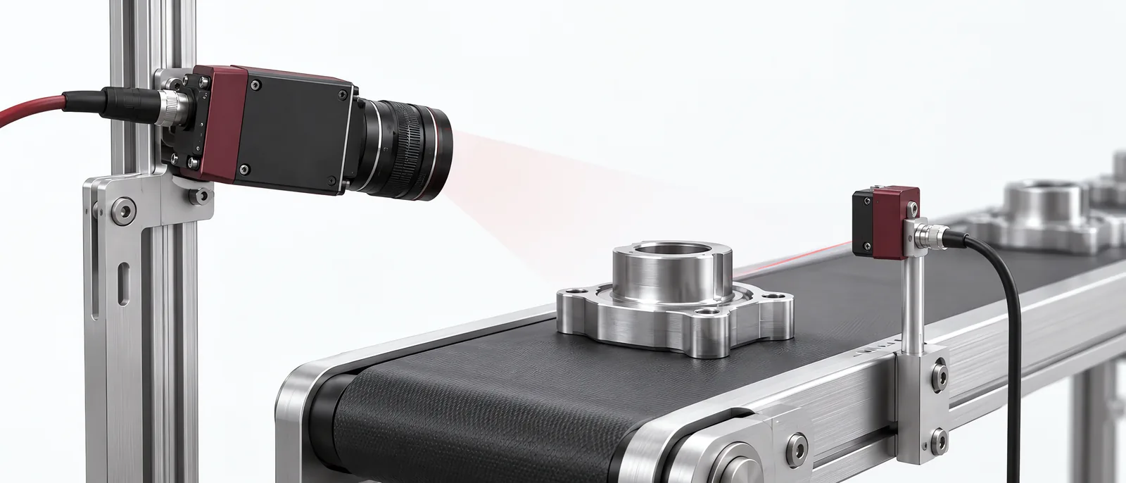
Conceptual equipment illustration.
A machine vision camera must capture a useful image at the correct moment and deliver it before the inspection decision is needed. Pixel count alone cannot establish that. Start with the smallest feature, the movement during exposure and the required inspection rate; then match the camera to the lighting and host interface.
The acquisition hardware is one part of a machine vision inspection system. Our machine vision inspection guide covers the wider decision, including defect definitions and rejection.
Calculate the Movement During Exposure
Basler’s image-quality guidance explains that a longer exposure collects more light but can increase motion blur and reduce frame rate. Increasing gain also makes noise more visible. Set exposure and gain separately, then compare the detail and noise in the acquired image.
For a worked example, assume a part moves at 500 mm/s, exposure lasts 0.2 ms and image sampling is 0.05 mm/pixel:
- Movement during exposure = 500 × 0.0002 = 0.1 mm.
- Image displacement = 0.1 ÷ 0.05 = 2 pixels.
Those assumptions produce two pixels of movement; they do not establish an acceptable limit. Compare that displacement with the feature being inspected. A broad missing-part check and a fine edge measurement can need different exposures. Test real moving parts with the proposed light, aperture and exposure together.
Trigger the Image, Not Just the Inspection Software
Document where the part-present signal originates, how it reaches the camera and when the exposure actually starts. Include sensor delay and position variation. A software request sent through a busy PC can have a different timing path from a hardware trigger.
Check the sensor’s shutter behaviour with moving objects. Global and rolling shutter architectures expose/read the image differently; the resulting geometry depends on the device and acquisition mode. A catalogue frame rate cannot demonstrate undistorted measurement in your application.
Trigger bursts, long idle periods and closely spaced parts deserve separate tests. The camera should report acquisition status so that a missed image cannot become a passed part.
Budget the Data Path
An assumed 2,448 × 2,048 monochrome image at 8 bits/pixel contains about 5.0 MB before transport overhead. At 30 images/s, raw image traffic is roughly 150 MB/s. This calculation excludes protocol overhead, padding and other cameras sharing the interface.
Use the actual pixel format and region of interest when checking sustained transfer. Record dropped frames, trigger counts and decision latency under the production configuration, including image storage if it is enabled.
A smart-camera versus PC-vision comparison helps establish where processing and storage belong. If the feature requires height information, first resolve the 2D versus 3D measurement decision; adding pixels to a 2D camera does not create depth data.
Discuss the image-acquisition task with Motionwell, including what the camera needs to see and when the result must reach the machine.