
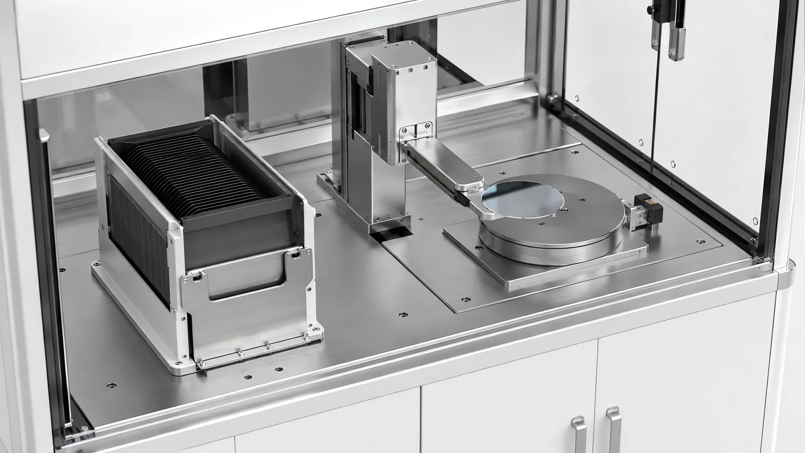
Motionwell designs wafer handling automation in Singapore for controlled transfer between carriers and process stations. Substrate size, allowable contact area, ESD requirements and the cleanroom interface set the tooling and motion design. The system combines carrier mapping, alignment, presence verification and recovery logic with the process tool’s handshake.
Design, assembly and testing take place at Woodlands Link. Related cleanroom automated test equipment illustrates our work on filtered enclosures, automated docking and test-data handling.
What we design and build is the machine between and around process tools: the frame, the motion, the tooling, the enclosure and its airflow, the control system, the recovery logic and the record. The general cleanroom engineering underneath all of it is on our cleanroom automation equipment page.
Why Is Wafer Handling a Contamination Problem Before It Is a Motion Problem?
The motion is the easy part, and easier than the specification usually suggests. A wafer moves a short distance, in a plane, slowly, with almost no mass, along a path that never changes. What is being bought is a machine that performs that trivial move a very large number of times without touching the wrong surface, without shedding, without charging the disc, without cracking it, and without needing a person to reach inside.
The economics explain the asymmetry. A wafer arriving at a mid-line transfer step carries the accumulated cost of every process step already performed on it, and it carries that cost across its whole active surface. A machine that drops it destroys all of that at once, and a machine that lands a particle on it may destroy some of it silently, with the loss appearing at electrical test weeks later against a cause nobody can now identify. That is the same silent failure signature we design around on electronics test work.
That sets the order the machine gets designed in. The contamination boundary comes first, because it fixes the enclosure, the airflow and where the mechanism may live. The contact scheme comes second, because it fixes the end effector and with it the acceleration budget. The mechanism is drawn third, against those two. Reversing the order produces a fast handler that cannot hold its class, and the fix is a new frame.
What Do the Carrier and Its Interfaces Settle Before the Machine Is Drawn?
They settle more than the robot choice does. The carrier decides where the wafer meets room air, and that single answer sets the size and cost of the clean envelope.
| What the material arrives in | What it is | What the machine has to provide |
|---|---|---|
| Front opening unified pod (FOUP) | A sealed carrier, opened only at a load port, so wafers never see room air in transit | A load port with door handling, a mapping sensor, and a clean envelope that only has to cover the transfer path |
| Sealed pod with a bottom-opening interface (SMIF) | The same principle in a different geometry for smaller formats | The same door-handling problem, resolved against a different opening direction |
| Open cassette | A slotted carrier with no door, so the wafers breathe whatever air surrounds them | A clean envelope over the whole machine, beyond the transfer path |
| Carrier delivered by overhead or floor transport | A drop-off at a defined position | A load position with presence and orientation sensing, and an interlocked handshake before either side moves |
| Handoff signalling between transport and load port | The parallel I/O interlock the two sides have to agree on | Correct sequencing and, more importantly, a named owner for the signals |
| Equipment-to-host messaging | SECS/GEM, the standard route for equipment state, events and per-unit data | A control architecture that can report state as events |
Two points from that table are where projects actually go wrong.
Slot mapping happens before motion or it happens too late. A cross-slotted or double-slotted wafer that is discovered by a blade already entering the carrier is a broken wafer and possibly two. The map is taken first, the machine refuses to start on an ambiguous map, and that refusal has to survive the pressure to switch it off once the line is running.
Interfaces need an owner named in writing. Every row above is a boundary between two suppliers, and each is a place where both can reasonably assume the other holds it. The cheapest place to fix that is the specification, which is what our guide to writing an automation URS is for.
Which End Effector Holds a Thin Brittle Disc, and What Does Each Cost?
The choice is decided by which surface is allowed to be touched. Once that is answered, the rest follows.
| End effector | How it holds | What it touches | What it costs you |
|---|---|---|---|
| Passive support blade | Gravity and friction alone, on a flat paddle | The back surface, over the whole pad footprint | Acceleration is capped by friction, and there is no grip signal to verify, so a slip is discovered by its consequences |
| Vacuum blade | A sealed area under the back surface, held by pressure difference | The back surface, with the largest contact print of the three | Needs a flat, clean, sealable back face. A leak is not a weak grip, it is no grip, so the vacuum level has to be monitored |
| Edge grip | Actuated contact on the wafer edge only, clamping laterally | The edge exclusion zone, with both faces clear | An actuator, its utilities and its wear on the blade, a wider swing envelope, and a much tighter requirement on where the wafer sits before the fingers close |
| Bernoulli | A gas flow across the front face producing a low-pressure region that lifts without contact | Nothing, or edge stops only | A continuous supply of clean dry gas, high flow moving directly over the product surface, and lateral instability unless the wafer is constrained |
The Bernoulli row deserves its own sentence because it is often specified for the wrong reason. Non-contact is not the same as low risk. The tool works by moving a lot of gas immediately above the active surface, which means the cleanliness of that gas and of everything the flow can reach becomes product quality. A non-contact effector in a machine whose airflow was never designed for it can move more contamination onto a wafer than a clean vacuum pad would.
Whichever family wins, blade materials are chosen for the environment as much as for stiffness: engineering plastics such as PEEK and technical ceramics behave inside a clean zone, while painted or powder-coated parts are a particle source that worsens over the machine’s life. The wider treatment of tooling design, including how a grip is verified, is on our end of arm tooling page.
Why Is the Handoff Tolerance Tighter Than the Transport Tolerance?
They are two different requirements that get written as one number. Transport tolerance is a clearance question: the blade has to enter and leave a slot without scraping, and the wafer has to stay on the blade. Handoff tolerance is a capture question: the wafer has to land inside the acceptance range of a chuck, a pocket or a set of lift pins, and that range is far smaller than the slot clearance.
The number people quote is robot repeatability, and it is one term in a chain that also holds teach point accuracy, blade deflection under load, where the wafer actually sat on the blade, carrier slot position, the station datum, and thermal growth between a cold start and hour six. Repeatability is usually the smallest of them. Budgeting the chain is what makes a handoff as reliable at hour six as at hour one.
Orientation is the second half of the problem and it is not solved by position. Downstream steps need the wafer’s rotational orientation known, and the wafer does not remember it. An aligner rotates the disc under a sensor, finds the notch, or the primary flat on older formats, along with the centre offset, and reports a correction the robot applies on the next move. Two consequences follow. It is a serial step unless the layout buffers it or a second arm covers it. And it is a measurement, so it also reports how far off-centre the wafer arrived, which is a free early warning about a drifting station, and it is lost wherever that report is not logged.
The related principle on our sensor panel line is vision compensation: the camera measures X, Y and rotation offset, and the controller checks the correction before shifting the robot trajectory. For wafer alignment, the inspection recipe also checks notch visibility and geometry, then routes a damaged or obscured feature to a defined recovery sequence. Fixture stability, lighting and the permitted correction range are established together. The vision-guided SCARA panel assembly case study shows the offset-correction approach; our machine vision inspection page explains calibration and sample testing.
What Does a Particle Class Do to the Drives and the Cables?
It moves them. The mechanism sheds as it wears, and on a handler it sits directly above the product for the whole stroke, so it goes below the product plane, behind a seal, or both, with pneumatic exhaust ducted away. Those choices, and the material, finish and lubricant decisions attached to them, are the same for any machine holding a class and are covered in the cleanroom machine design guide.
Two consequences are specific to this work and worth adding here.
Moving the servo drives outside the enclosure, which is the standard answer for a particle source with its own cooling fan, buys longer shielded motor cables. In a machine that also has a static control requirement, those cables are where grounding and electromagnetic compatibility start to argue with each other: the shield wants one defined path to ground, the ESD scheme wants every accessible surface bonded, and resolving both without creating a ground loop is a design task at schematic stage, never a wiring decision on the shop floor.
And the airflow has to survive the machine’s own motion. A blade sweeping across a wafer drags air over the product surface, so the downflow path over the transfer route has to be genuinely clear. That constraint fixes where frame members, cable trays and overhead tooling can sit, which makes it a layout decision.
Why Is Static a Design Input and Not an Accessory?
Charge is generated by the machine doing exactly what it was built to do. A wafer lifting off a blade is separation. A carrier door opening is separation. A belt turning, a plastic guide rubbing, dry filtered air moving fast over a surface: all generate charge, all are designed in, and all happen long after a bill of materials was signed with “ESD-safe materials” written on it.
The useful design question is not which materials are safe but which electrical role each surface has to play, because the answers conflict.
| Electrical class | Where it appears in our work | The role it plays | What goes wrong when it is used in the wrong place |
|---|---|---|---|
| Insulative | Nylon and POM specimen nests on the cleanroom test equipment, surface resistivity exceeding 10^12 ohm | Keeps the fixture from loading or shorting the device during resistance and continuity measurement | An insulator cannot bleed a charge. Rub it and it holds what it collects until something else provides the path |
| Dissipative | Carbon-fibre-loaded PVC conveyor belting at 10^6 to 10^9 ohm, dissipative classification per IEC 61340-5-1 | Bleeds charge to ground gradually | Useless without a real path to ground behind it, which is the part that gets value-engineered out |
| Grounded and bonded | Conveyor frames bonded to the facility ground bus with straps at every 3 metre interval on our battery line | The return path every other measure silently assumes exists | A bonded frame with an insulating coating between the bond and the working surface is decoration |
| Ionisation | Grounded workstations with ionisers on our electronics handling work | Neutralises charge on things that cannot be grounded, including the product itself | An unbalanced or unmaintained ioniser is a charge source, so it needs a verification routine, beyond an installation date |
The first two rows together make the point that a materials list cannot. A test fixture wants insulation so the measurement is not loaded, and the handling path wants dissipation so charge cannot accumulate. Both are correct, they are not the same part, and deciding which is which surface by surface is engineering. That conflict is invisible on a specification asking only for ESD-safe construction, which is why we treat the static scheme as a drawing. The electronics context for that work sits on our electronics and semiconductor automation page.
What Happens After a Wafer Breaks?
It will break eventually, and what the machine does next decides whether the cost is one wafer or a shift.
Fragments go where the geometry and the airflow send them: into the slot, along the blade, down into whatever is under the transfer plane, and onto the wafers still in the carrier. That is why a machine that stops in place and holds its state is worth more than one that completes the commanded move. The questions somebody needs answered immediately are which wafer, which slot, whether anything is still on the blade, whether the rest of the lot is suspect, and whether the machine can be opened without dragging debris further into the clean envelope.
Designing for that answer costs little at concept and cannot be added later. A defined safe stop that does not finish the move. Blade and slot geometry a person can actually see into with a torch. Service access from the non-clean side wherever the mechanism allows, with a documented re-clean where a panel must open into the clean zone. Captured fasteners, so nothing else joins the debris during recovery. And an event record holding the last commanded position and the last confirmed sensor state, because the machine will be cleaned before anyone gets round to diagnosing it.
Restart is the part that gets skipped. A machine that resumes by trusting its memory of where it was is not safe after a breakage. It has to re-map the carrier, re-verify presence at every station it believes is occupied, and require a positive human acknowledgement before it moves. That sequence is written once, at design time, or it is improvised at three in the morning by whoever is on shift.
Recovery is also the safety case, because it is the scenario that puts a person inside a machine with servo axes and stored pneumatic energy. Where a robot is inside the enclosure, the robot falls under ISO 10218-1 and the integrated system under ISO 10218-2, with each safety function carrying a required performance level under ISO 13849-1, calculated and validated. The guarding and validation scope that follows is on our machine safety and CE marking page. The figure worth asking any supplier for is not a mean time between failures but how long a recovery takes and who is qualified to perform it, because inside a clean envelope the recovery includes the re-clean.
Where Do the Seconds Actually Go on a Transfer Machine?
They go somewhere other than where the datasheet suggests. The arithmetic is simple and it is easy to skip before a robot is chosen.
| Element of the cycle | What it is | Does it overlap the process |
|---|---|---|
| Carrier dock, door open, slot map | Fixed overhead once per lot | No, and it is charged to every lot regardless of size |
| Station to carrier move, unloading the finished wafer | Per wafer | No. The station is idle throughout |
| Carrier to station move, loading the next wafer | Per wafer | No. The station is still idle |
| Alignment | Per wafer | Only if it is buffered or handled by a second arm |
| Settling and hold verification before release | Per wafer | No, and it is a step often left out of an estimate |
| Process time at the station | Per wafer | This is the number the whole machine exists to protect |
| Assists and exception handling | Unpredictable | This is why the measured rate differs from the calculated one |
For the serial exchange in the table, cycle time is process time plus unloading, loading and the checks that keep the station idle. With a second blade, buffered alignment or parallel stations, some handling can overlap processing. Draw the timing chart to identify the remaining non-overlapping steps before choosing a faster axis. Acceleration is then sized against substrate retention and the permitted mechanical stress.
The number that decides your real output is assists. A machine that indexes beautifully and needs a person twice a shift produces less than a slower one that does not, and the difference rarely appears in a specification. Ask for a mean time between assists during acceptance, and write the measurement method into the protocol before the machine is built. The same argument on a multi-station tester is worked through on our automated test equipment page.
What Does a Per-Wafer Record Have to Carry?
The unit of record is the wafer, not the lot or the carrier, and that decision belongs in the control architecture, never in a reporting layer bolted on afterwards.
A useful record binds an identity to a place and a history: which wafer, which carrier and slot it came from and returned to, which station and which arm handled it, timestamps at each transfer, the alignment correction that was applied, and every exception including the ones the machine recovered from on its own. That last pair is where the value sits. A correction that drifts on one station over three weeks is a mechanical fault reporting itself long before it becomes a broken wafer, and a machine that applies the correction without logging it has thrown that warning away.
The architecture is one we have delivered on a different unit of record. On the cleanroom test equipment, pallet identification uses RFID tags embedded in the pallet body so the PLC tracks each specimen’s position and test status around the loop, force, displacement, resistance and continuity are logged per serial number, and export runs as CSV by batch for offline Cp/Cpk study or over OPC-UA for live charting on whichever SCADA platform the plant already runs. Publishing over OPC-UA, instead of writing into one named SCADA product, is the decision worth copying there: what the machine owes the plant is a tag list and a data model anything can subscribe to, and a machine that can only feed one vendor’s client is the reason a site later finds it cannot change its SCADA. Substitute the wafer for the specimen and the carrier slot for the pallet, and the structure is unchanged.
One caution decides whether any of it is worth keeping. A record is only as good as its identity binding. If the machine infers which wafer it is holding from a slot position, and anything re-orders the carrier between two operations, every downstream record is confidently wrong and nothing flags it. Bind to a read wherever the substrate carries a readable mark; where it does not, the binding lives in the carrier and the slot, and the machine has to stop on the ambiguous case. How that binding is designed and verified generally is on our code reading and traceability page.
When Is a Catalogue Tool the Better Answer?
Wherever the work is standard, which covers most of this equipment category. A standard wafer in a standard carrier, moving between standard load ports, being sorted, transferred or inspected, is a mature product category with established vendors, regional spares and a large installed base. A machine drawn from scratch rarely competes on price, lead time or the odds of working in week one.
Custom work earns its place at the edges of that description, and the edges are specific. The substrate is not a standard wafer, so it is a panel, a carrier tray, a frame of singulated die or a non-round part nobody sells a handler for. The transport runs between tools never designed to talk to each other, which makes the interface the project. The machine has to do something as well as move, meaning test, measure, mark or cure, which is the shape of our delivered electronics work. A working legacy tool has no usable interface, so the real choice is a bridge or a replacement, covered on the legacy machine connectivity page. Or the binding constraint is the building. How to run that decision is set out on our custom machine versus standard equipment page.
What Has to Be Settled Before Anyone Draws the Machine?
Seven questions, in this order. The first that gives a hard answer usually reshapes everything after it.
- What is the substrate, and which surfaces may be touched? This settles the end effector family, and with it the acceleration budget.
- What does it arrive in, and where does it meet room air? Sealed carrier or open cassette decides whether the clean envelope covers a path or a machine.
- What is the station’s capture range at the handoff? Not the robot’s repeatability, but the capture range and the tolerance chain that has to fit inside it.
- Does anything downstream need known orientation? If it does, alignment is a station in the layout and a step in the cycle.
- What is the process time at each station? Handling only has to fit inside it, and everything faster is money spent on nothing.
- What has to be true after a breakage? Where fragments go, who opens the machine, what gets re-cleaned, and what restart demands.
- What must be provable per wafer, and to which system? Decide it before the control architecture, because it is expensive to retrofit.
| Your situation | Start from | Why |
|---|---|---|
| Standard wafers, standard carriers, sorting or transfer between load ports | A catalogue tool from a semiconductor equipment supplier | A mature product beats a drawing on price, lead time and installed base |
| Non-standard substrate, or a carrier nobody sells a handler for | A purpose-built machine | There is no catalogue answer to compare against |
| Both faces of the substrate are process surfaces | Edge grip, or Bernoulli with edge stops | A back-surface pad is not available, and that decides the tool before the robot |
| The line runs, but somebody attends it twice a shift | Assist rate and recovery design | Sustained output is set by interventions |
| A working legacy tool with no usable interface | A connectivity bridge assessed against replacement | The interface is the project; the motion is the easy half |
Inter-station transport across a plant, well beyond one tool, sits on our warehouse and intralogistics page.
Standards Used in Machine Design and Validation
These references inform the design, testing and documentation described on this page. Each row links to its primary source and records the edition checked.
| Standard | Current edition | What it means for your machine |
|---|---|---|
| ISO 10218-1: Robotics, safety requirements, Part 1: industrial robots | ISO 10218-1:2025 | Published February 2025, the third edition and the first substantive revision since 2011. It adds robot classifications with matching functional safety requirements and safety-related cybersecurity requirements. Most of ISO/TS 15066:2016 on collaborative operation moved into Part 2.Checked 12 Sep 2026 against ISO 10218-1:2025 (iso.org/standard/73933.html) |
| ISO 13849-1: Safety of machinery, safety-related parts of control systems | ISO 13849-1:2023 | Provides the design method for safety-related control functions, including architecture, component reliability, diagnostic coverage and common-cause failure measures. The machine risk assessment establishes the required Performance Level; design calculations and validation provide the evidence for each function.Checked 1 Sep 2026 against ISO 10218-1:2025 normative references |
Frequently Asked Questions
What does Motionwell provide for wafer handling automation?
Motionwell designs and integrates cleanroom-compatible transfer equipment around the substrate, carrier and process-tool interfaces. Scope includes servo motion, ESD-safe tooling, enclosure airflow, carrier mapping, recovery logic and equipment data exchange. Acceptance criteria cover handling success, cycle time, particle performance and recovery under the agreed operating conditions.
Can a substrate handling machine be changed over to a different wafer size later?
Assume not without significant rework, and price the alternative while the layout is still on paper. Carrier interface, slot pitch, blade geometry, edge-grip finger positions, aligner chuck, teach points and the whole tolerance chain are sized around one substrate. What normally survives a size change is the frame, the enclosure, the control architecture and the software. What does not survive is everything that touches the wafer. Where two sizes are genuinely in the plan, say so at concept: designing for both from the start changes the envelope of the machine, and it is cheaper than retrofitting the second one afterwards.
What can a factory acceptance test actually prove about a cleanroom handling machine?
FAT covers motion, sequencing, interlocks, recovery behaviour and the data record. Particle testing is planned against the agreed operating conditions, including motion at production speed, sampling locations and the surrounding environment. The acceptance plan assigns the factory and site checks, and sampling access is designed into the enclosure from concept stage. Machines are built and tested at our Woodlands Link facility, where Singapore buyers can witness the run. Standard builds take 16 to 24 weeks from concept approval to FAT; projects with cleanroom compatibility or full validation documentation take 24 to 32 weeks.