
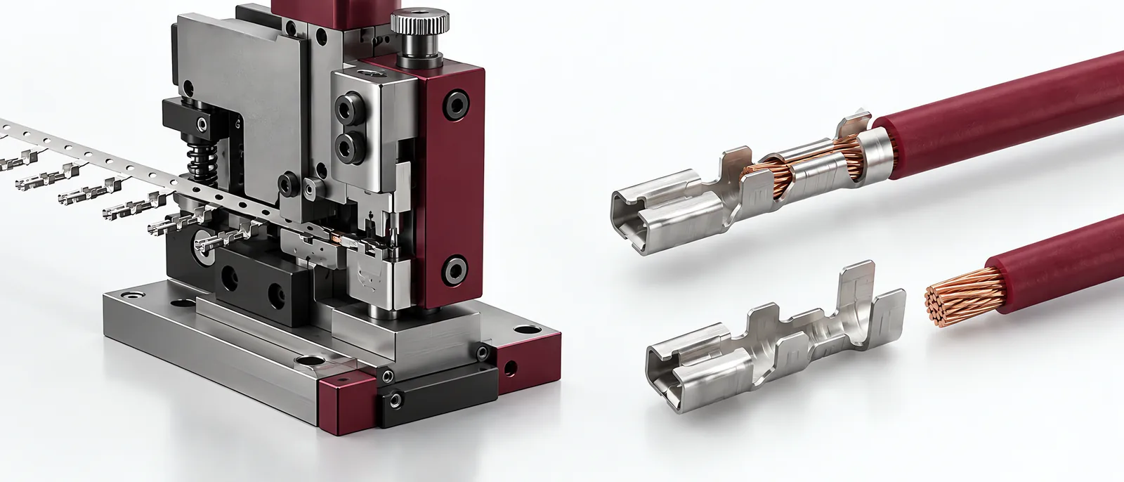
Conceptual equipment illustration.
A wire crimping machine must produce the terminal manufacturer’s specified termination on the intended conductor. Choose the applicator and tooling for that combination, including conductor construction and insulation dimensions. A machine cycle that reaches its endpoint is not, by itself, proof of a correct crimp.
For a custom automated station, wire preparation, placement and result handling belong in the same scope as the press.
Keep the Wire and Terminal Pair Identifiable
Record terminal part number, wire construction, conductor size and the accepted preparation. Similar-looking terminals can require different tooling or setup. Changing wire strands or insulation can change the process even when the nominal size remains the same.
TE Connectivity’s crimp-height paper explains the relationship between crimp geometry, conductor properties and mechanical/electrical performance. It also discusses why a pull test and force monitoring each reveal different aspects of the termination.
Use the selected terminal’s application requirements for its crimp dimensions and inspection limits. Do not copy a limit from another terminal family.
Define Complementary Checks
| Check | What it contributes |
|---|---|
| Strip/placement inspection | Correct conductor presentation before crimping |
| Crimp height or specified geometry | Conformance to the terminal’s dimensional requirement |
| Force/displacement monitoring | Variation in the performed forming cycle |
| Pull testing | Specified mechanical retention under its test conditions |
| Electrical testing | The electrical characteristic required for the assembly |
A stronger pull result is not permission to over-compress the conductor. The trial should demonstrate the accepted process window, including the consequences of incorrect settings.
For the electrical assembly, hipot testing concerns insulation withstand, not the contact resistance of a single crimp. Name the required electrical characteristic and the method that measures it.
Make Abnormal Samples Part of the Trial
Include incorrect strip length, displaced wire, missing terminal and the permitted material variation. Use these samples to establish what the station detects and what remains controlled through upstream preparation or sampled inspection.
After an applicator change, identify the installed tooling and run the prescribed setup checks. A stored recipe must match the actual applicator. Record the validated setup with the accepted reference samples.
The automated test equipment interface can associate each termination or assembly with its result. For an electronics production workflow, define whether traceability belongs to individual wires, a harness or the completed product.
Talk to Motionwell about the termination station to connect preparation, crimping and verification.