
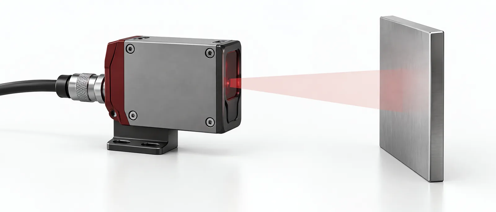
Conceptual equipment illustration.
An IO-Link sensor combines a measurement function with a defined digital data interface. Choose the measurement first, then confirm which values, parameters and diagnostic events the device exposes. The IO-Link label does not mean that every sensor supplies raw signals or every internal calculation.
For machine retrofit and modernization, this keeps the sensor specification tied to the maintenance or production decision it needs to support.
Begin with the Physical Measurement
A pressure sensor still needs the appropriate range, media compatibility and installation. A distance sensor still needs suitable target and optical conditions. IO-Link changes the communication route; it does not remove those measurement requirements.
Record the useful measured variable, units and valid operating range. Separate that variable from a device’s switching output or internally derived status. They may support different tasks.
For an existing machine, the legacy-connectivity scope establishes whether the sensor is a new measurement source or a replacement for an existing input. Preserve the control function while introducing the intended data path.
Use the IODD to Interpret the Device
The IO-Link System Description explains the device description, process data and acyclic device data/events. Match the IODD and interpretation to the actual device identity and revision.
Do not read an integer and assume it is already a value in engineering units. Check data structure, scaling, signed values and validity information. A wrong scale can produce plausible-looking trends that are still incorrect.
Include a known reference condition in the commissioning trial. Compare the physical measurement and the value shown by the receiving application. Record how over-range, under-range and device-unavailable conditions appear.
Check Timing Through the Complete Path
The device’s measurement update and IO-Link communication cycle are not necessarily the same as the rate at which a server stores data. The system description also identifies device cycle time and master processing as parts of the response path.
Define the required application interval. A slow temperature trend and a short process transient need different acquisition evidence. If the device exposes only a processed periodic value, increasing server polling will not recover an unavailable raw waveform.
Make Replacement Testable
Record the accepted replacement identity and the required settings. If the selected master supports parameter restoration, check its configuration and then verify the measurement after replacing the device. Successful communication alone does not establish the correct range or setpoint.
For an automated test equipment interface, preserve measurement validity with the value and specimen identity. Do not replace an unavailable value with zero unless zero is explicitly the correct defined behaviour for that condition.
A sensor can support a downtime-reduction workflow when its reading is associated with the relevant machine, operating state and maintenance event.
Contact Motionwell about the measurement to plan the sensor, interpretation and collection path together.