
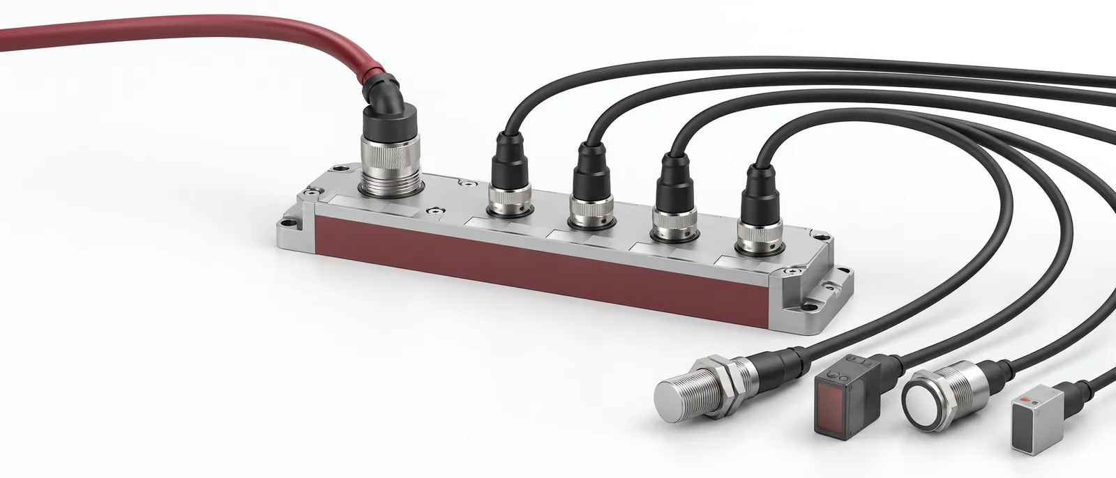
Conceptual equipment illustration.
An IO-Link master connects IO-Link devices to the controller or data system through individual device ports. Select it from the devices, their power requirements and the upstream interface you need. The number of ports alone does not tell you whether the required sensor values and diagnostics will reach your application.
This is a practical component of machine retrofit and modernization. For equipment with mixed interfaces, the legacy-machine connectivity scope covers the wider collection path.
Separate the Device Link from the Network Interface
The IO-Link System Description describes point-to-point device connections, cyclic process data and separate device parameters/events. The master connects that device-level exchange to the chosen automation architecture.
Check the specific master model’s upstream protocol and supported data-access functions. An IO-Link device does not become an Ethernet device simply because the master has an Ethernet connector. Nor does every master automatically provide the same northbound MQTT, OPC UA or API functions.
For a purchase specification, identify the path explicitly: sensor, master port, upstream interface, controller/gateway and destination. State who interprets the device data at each step.
Check Port Class and Power
The system description distinguishes Class A and Class B ports. Class B provides an additional isolated supply arrangement for devices with greater power demand. Confirm the pin assignments, cabling and supply limits of the actual master and device; do not connect solely from matching connector size.
Prepare a port schedule that identifies:
| Item | Why it belongs in the specification |
|---|---|
| Device model and port | Unambiguous device assignment |
| Port mode/class | Correct communication and supply arrangement |
| Device current and total supply | Power budget for the installed configuration |
| Process-data structure | Byte/bit interpretation and engineering units |
| Parameters and events needed | Data beyond the normal cyclic value |
Map device identities and available process values into the machine-monitoring system. Keep the master port schedule with that mapping; an application needs to know which source produced each value.
Prove What Reaches the Destination
Create a trial with a known changing process value and an intentional device-unavailable condition. Verify the value, units and invalid status at the destination. A communication-ready light is not proof that the application decoded the data correctly.
Test the device parameters and diagnostic events needed by the operating task. Available content depends on the device and interface; IO-Link does not guarantee access to every internal waveform or algorithm.
Then test device replacement under the selected master configuration. Identify whether parameter storage/restoration is supported and enabled, which identities are accepted and what still needs verification after replacement.
Keep Acquisition and Use Distinct
The PLC programming scope should define the controller mapping and response to unavailable device data. The master supplies a data path, but the application still needs to identify the machine, operating state and relevant time.
Discuss IO-Link integration with Motionwell, including the values and events the maintenance, production or AI task needs to use.